Overview
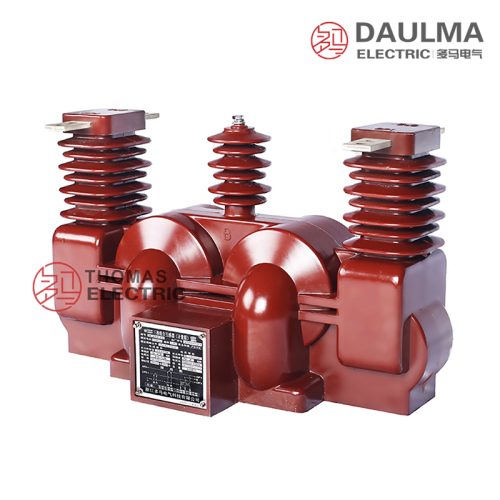
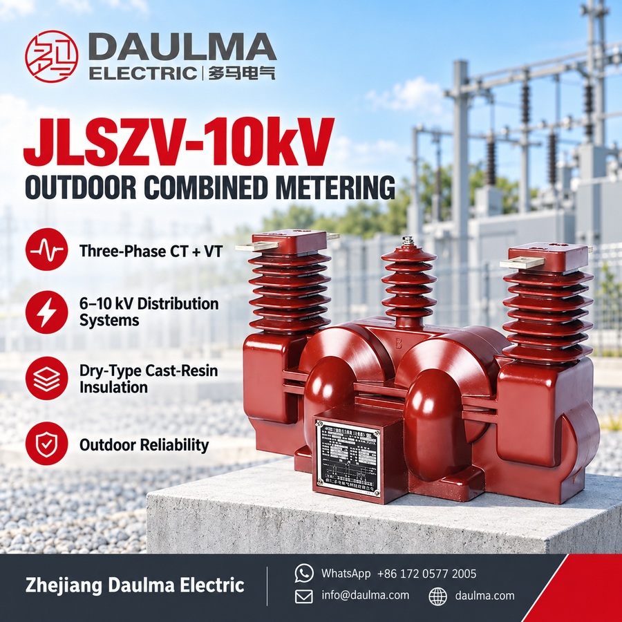
The JLSZV-10kV is a three-phase outdoor dry-type combined instrument transformer designed for 6 kV and 10 kV medium-voltage distribution systems. It features fully enclosed epoxy resin vacuum-cast insulation, providing high dielectric strength, moisture resistance, and long-term outdoor reliability without oil or maintenance.
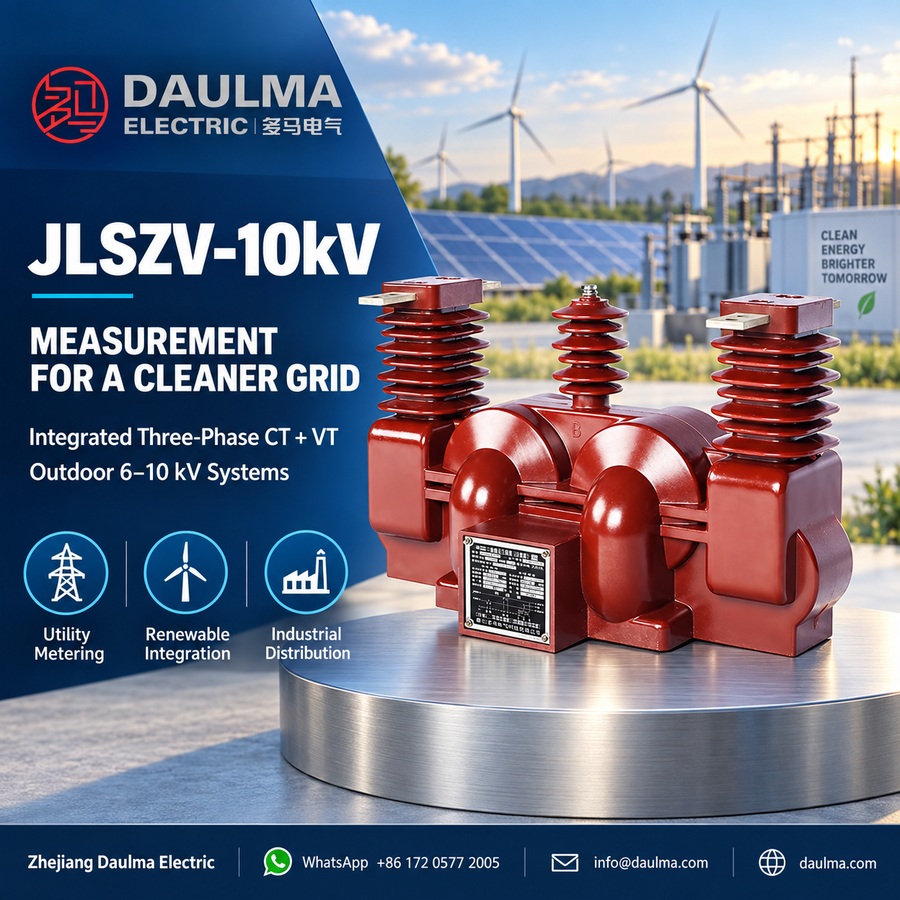
Engineered for precision metering and system monitoring, it meets IEC 61869, GB/T 20840, and DL/T 866 standards. The unit delivers VT accuracy classes of 0.2 or 0.5 and configurable CT ratios, making it suitable for revenue-grade energy metering, grid modernization, industrial power monitoring, and renewable energy integration in polluted or exposed outdoor environments.
Key Ratings Snapshot
| Parameter | Rating |
|---|---|
| System voltage class | 6 kV / 10 kV |
| Rated frequency | 50 Hz (60 Hz optional) |
| VT connection | V/V (three single-phase units) |
| VT secondary voltage | 100 V |
| VT accuracy class | 0.2 / 0.5 |
| VT rated output | 2 × 15 VA (0.2) / 2 × 30 VA (0.5) |
| CT secondary current | 1 A, 2 A, or 5 A |
| Insulation level | 1.2/42/75 kV (power freq / lightning / switching) |
| Creepage distance | 440 mm |
| Insulation material | Epoxy resin cast (outdoor-grade) |
| Installation | Outdoor, pole or ground mounted |
| Applicable standards | IEC 61869-1/-2/-3; GB/T 20840; DL/T 866 |
Model Designation
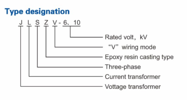
- J: Combined instrument transformer (voltage + current)
- L: Current transformer component
- S: Three-phase configuration
- Z: Outdoor support (pillar/post) type mounting
- V: Voltage transformer with V/V connection
- 10: Voltage class (kV), for 6 kV and 10 kV systems
Construction
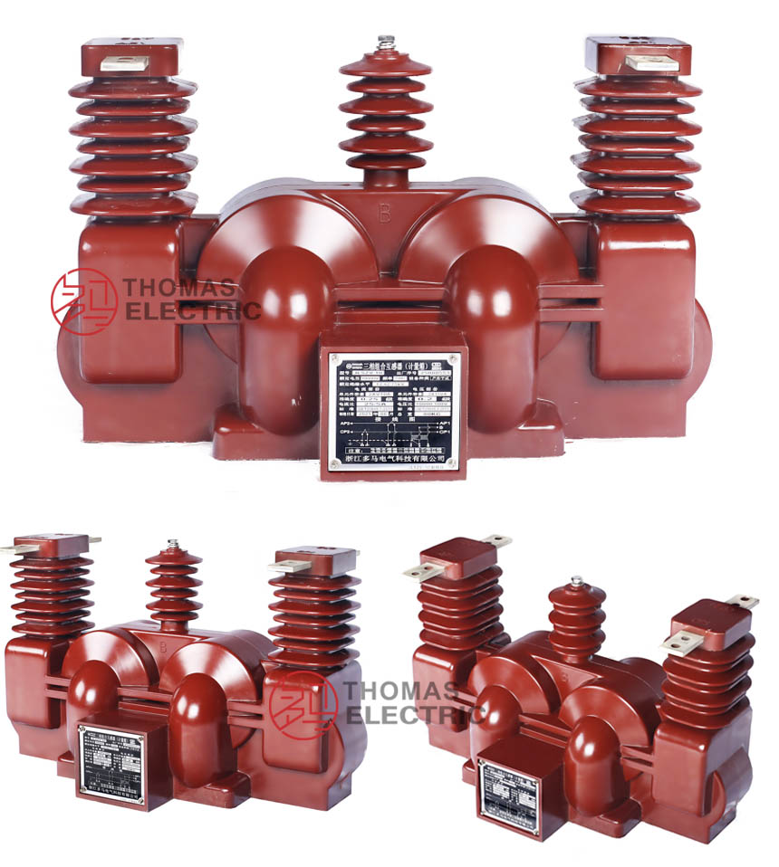
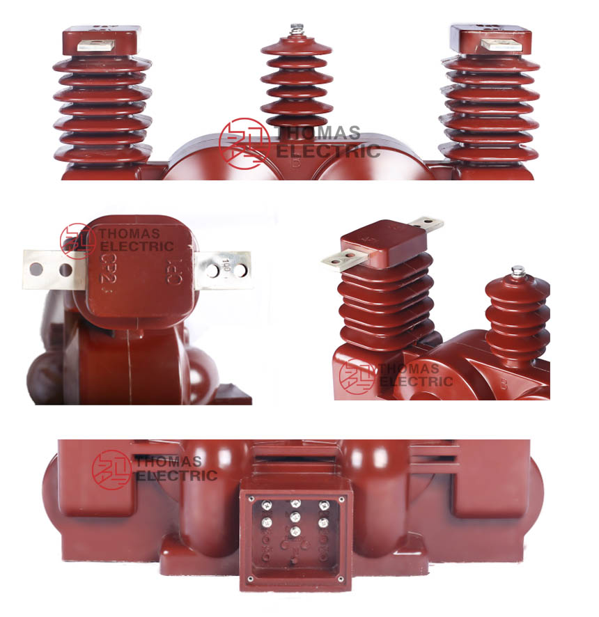
The JLSZV-10kV features a robust outdoor support (post) type structure suitable for pole or ground mounting. Its core components include laminated silicon-steel cores for the voltage transformers and toroidal magnetic cores for the current transformers, all fully encapsulated in vacuum-cast epoxy resin using an outdoor-grade formulation. This construction ensures void-free insulation with excellent mechanical strength, UV resistance, pollution resistance, and long-term dielectric stability under thermal cycling and harsh weather conditions. The design is maintenance-free, requiring only periodic external cleaning, and eliminates environmental risks associated with oil-filled alternatives. Terminal markings comply with IEC 61869 and GB/T 20840 polarity conventions for accurate metering and protection coordination.
Technical Parameters
Service Conditions
- Installation environment: Outdoor installation (pollution-resistant epoxy resin construction)
- Altitude: Not exceeding 1000 m above sea level (higher altitude ratings available upon specification for engineering confirmation)
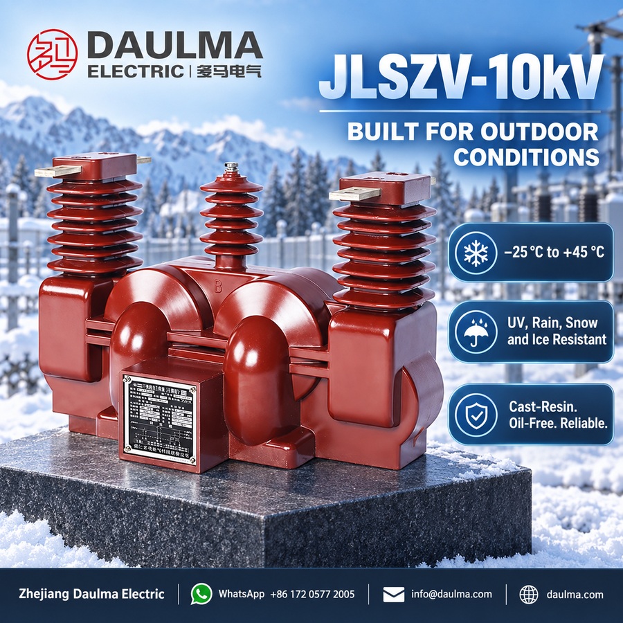
- Ambient temperature: −25 °C to +45 °C (outdoor service range)
- Relative humidity: Daily average ≤ 95%, monthly average ≤ 90% (at +20 °C reference)
- Pollution level: Suitable for moderate to heavy pollution environments (creepage distance 440 mm minimum)
- Environmental conditions: Resistant to UV radiation, rain, snow, ice, and atmospheric pollution; no explosive or flammable atmosphere; designed for typical outdoor distribution system conditions
- Seismic conditions: Earthquake resistance per local grid requirements (shall be specified at ordering)
Technical Parameters
The JLSZV-10kV is a three-phase outdoor dry-type combined instrument transformer for 6–10 kV AC distribution systems (50 Hz), featuring cast-resin insulation, an operating temperature range of −25 °C to +45 °C, and suitability for altitudes up to 1000 m. It complies with standard medium-voltage instrument transformer requirements and supports primary current ranges from 5 A to 1000 A.
Voltage transformer Data
| Type | Voltage Ratio(V) |
Accuracy class / Rated secondaryoutput (VA) |
Limit output(VA) |
Rated insulationlevel(kV) |
|---|---|---|---|---|
| JLSZV(F)-6W | 6000/100 | 0.2—2×20 0.5—2×50 1.0—2×80 3.0—2×200 |
2×400 | 7.2/32/60 |
| JLSZV(F)-10W | 10000/100 | 0.2—2×20 0.5—2×50 1.0—2×80 3.0—2×200 |
2×400 | 12/42/75 |
Current transformer Data
| Rated primary current(A) |
Single ratio |
Accuracy class / Rated secondaryoutput (VA) |
1s thermal current(kA) |
Rated dynamic current(kA) |
||
|---|---|---|---|---|---|---|
| (0.2)S | 0.5S | 0.5 | ||||
| 7.5-10-15 | 7.5 | 1.0 | 2.5 | |||
| 10-15-20 | 10 | 1.5 | 3.75 | |||
| 15-20-30 | 15 | 2.4 | 6.0 | |||
| 20-30-40 | 20、25 | 10 | 10 | 15 | 3.0 | 7.5 |
| 30-40-50 | 30 | 10 | 10 | 15 | 4.5 | 11 |
| 40-50-75 | 40 | 10 | 10 | 15 | 8 | 20 |
| 50-75-100 | 50 | 10 | 10 | 15 | 9 | 22.5 |
| 75-100-150 | 75 | 10 | 10 | 15 | 12 | 30 |
| 100-150-200 | 100 | 10 | 10 | 15 | 16 | 40 |
Current transformer Data
| Rated primary current(A) |
Single ratio |
Accuracy class / Rated secondaryoutput (VA) |
1s thermal current(kA) |
Rated dynamic current(kA) |
||
|---|---|---|---|---|---|---|
| (0.2)S | 0.5S | 0.5 | ||||
| 150-200-300 | 150 | 10 | 10 | 15 | 24 | 60 |
| 200-300-400 | 200、250 | 10 | 10 | 15 | 32 | 80 |
| 300-400-500 | 300 | 10 | 10 | 15 | 45 | 100 |
| 400-500-600 | 400 | 10 | 10 | 15 | 60 | 100 |
Frequently Asked Questions
Q1: Can this 10kV combined transformer be installed at high altitudes?
Standard models support altitudes up to 1000 meters. For higher elevations, specify exact site altitude during ordering for engineering derating confirmation.
Q2: What is the maximum ambient temperature for outdoor installation?
The maximum ambient temperature is +45 °C, with a minimum of −25 °C. The cast-resin insulation ensures reliable performance across this outdoor service range.
Q3: Which pollution level is this outdoor dry-type transformer suitable for?
It is suitable for moderate to heavy pollution environments. The pollution-resistant epoxy resin construction provides a minimum creepage distance of 440 mm.
Q4: How are primary current ranges customized for this model?
Customization depends on your specific metering needs. The standard range supports 5 A to 1000 A primary current. Confirm exact ratios during ordering for factory calibration.
Q5: When should seismic resistance be customized for local grids?
Earthquake resistance is tailored to specific regional standards. Specify your exact seismic requirements at the time of ordering for factory engineering confirmation.
Q6: Are specific factory test reports provided before shipment?
Standard routine tests are performed prior to dispatch. Specific test scopes depend on project requirements. Contact our team for detailed certification documents.
Q7: Why choose this dry-type combined transformer over oil-filled models?
The JLSZV-10kV is a fully dry-type combined instrument transformer. It features cast-resin insulation, eliminating oil maintenance for typical outdoor distribution systems.
Installation & Wiring
Outline Dimensions
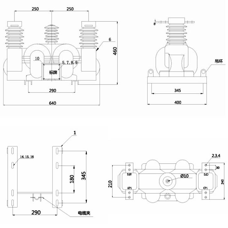
The outline dimensions shown in the drawing define the overall envelope, mounting hole locations, and interface points for pole-mounted or ground-mounted installations. Exact dimensional data is provided in project-specific drawings issued by the engineering team.
Selection & FAQs
Selection Guide
- Specify system voltage (6 kV or 10 kV) and ensure compatibility with local grid requirements.
- Select VT accuracy class (0.2 or 0.5) and rated burden based on connected metering equipment.
- Define CT transformation ratio, secondary current (1 A, 2 A, or 5 A), accuracy class, and burden to match system load and metering needs.
- Confirm short-circuit withstand capabilities (Ith for 1 s and Idyn peak) according to network fault levels.
- Indicate environmental conditions such as pollution level, altitude above 1000 m, seismic requirements, and mounting type (pole- or ground-mounted).
- Request enhanced features like extended creepage distance, high-altitude derating, or special terminal arrangements if needed for site-specific conditions.
Frequently Asked Questions
Q1: How do I correctly select the VT accuracy class (0.2 vs. 0.5) and burden for revenue-grade metering using the JLSZV-10kV in a 10 kV distribution system?
For revenue-grade metering per IEC 62053-22 and DL/T 448, VT accuracy class 0.2 is mandatory when billing accuracy uncertainty must not exceed ±0.2%. Class 0.5 is acceptable only for internal monitoring or non-billing applications. The JLSZV-10kV provides 2 × 15 VA at 0.2 class or 2 × 30 VA at 0.5 class—these are maximum continuous burdens. Exceeding them causes phase error and ratio error to degrade beyond class limits. Always calculate total secondary burden: sum VA ratings of all connected devices (e.g., kWh meters, RTUs, relays), then verify total ≤ rated output under minimum load conditions (e.g., 25% of rated voltage). For example, two 0.2-class meters each drawing 7.5 VA total 15 VA—acceptable for 0.2 class but marginal; include a 10–15% safety margin in design.
Q2: What are the key technical and operational advantages of the JLSZV-10kV dry-type combined transformer over oil-immersed or discrete CT/VT installations in outdoor 10 kV networks?
The JLSZV-10kV offers three critical advantages: (1) **Safety & environmental compliance**: Epoxy resin casting eliminates fire risk, oil leaks, and PCB concerns, meeting RoHS and IEC 61869-5 requirements for urban or ecologically sensitive sites. (2) **Space and installation efficiency**: Integrating three-phase CTs and V/V-connected VTs into one unit reduces mounting footprint by ~40% versus separate units and requires only one support structure, lowering civil works cost. (3) **Performance consistency**: Matched magnetic cores and identical thermal expansion coefficients ensure phase-to-phase ratio error <±0.1% and phase displacement <5 minutes—critical for AMI and synchrophasor applications. Additionally, its 440 mm creepage distance exceeds IEC 60815 pollution class III requirements, outperforming standard porcelain oil units in coastal or industrial atmospheres prone to flashover.
Q3: How do I interpret and apply the CT short-time thermal current (Ith) and dynamic current (Idyn) ratings when specifying the JLSZV-10kV for a 10 kV feeder with known fault levels?
The CT’s Ith (1-second RMS thermal withstand) and Idyn (peak electrodynamic withstand) must exceed the maximum prospective fault current at the installation point. For instance, if your system study shows a 3-phase fault current of 25 kA RMS (≈62.5 kA peak), you must select a CT primary range where Ith ≥ 25 kA and Idyn ≥ 62.5 kA. Referring to the JLSZV-10kV CT table, the 200–400 A range provides Ith = 32 kA and Idyn = 80 kA—sufficient for this scenario. Conversely, a 30–60 A CT (Ith = 4.5 kA) would fail catastrophically. Note that Ith scales with conductor cross-section and core mass; lower-ratio CTs inherently have lower withstand. Always validate against actual utility short-circuit studies—not nameplate switchgear ratings—as network topology affects local fault levels.
Q4: What are the most common installation errors that compromise safety or accuracy of the JLSZV-10kV, and how can they be prevented?
Three critical errors dominate field failures: (1) **Open-circuited CT secondaries during energization**—this induces lethal voltages (>10 kV) due to unopposed magnetizing current; always short and ground CT terminals before any work per IEC 61869-2 §7.3. (2) **Incorrect V/V VT phasing**—miswiring phase B or neutral leads to 173% metering error in apparent power; verify terminal markings (A/a, N/n per IEC 61869) and confirm phase rotation with a vector scope during commissioning. (3) **Insufficient clearance to grounded structures**—the 10 kV phase-to-ground impulse withstand is 75 kV; maintain ≥125 mm air clearance per IEC 60664 to avoid corona discharge. Additionally, install surge arresters within 1 m of the primary terminals and bond the transformer base to the station ground grid with ≤0.1 Ω resistance.
Q5: Can the JLSZV-10kV be customized for high-altitude (>1000 m), 60 Hz, or severe pollution environments, and what engineering trade-offs should be evaluated?
Yes, but with performance and cost implications. For altitudes >1000 m, dielectric strength derates ~1% per 100 m; above 2000 m, the standard 42 kV power-frequency withstand may require increased creepage (≥500 mm) or modified epoxy formulation with higher filler content. 60 Hz operation is supported, but core losses increase by ~15%, potentially reducing VT accuracy at light loads—burden must be re-rated downward by 10% to maintain class compliance. For severe pollution (IEC 60815 class IV), request extended creepage (≥630 mm) and hydrophobic silicone-modified epoxy. Customizations typically add 4–6 weeks to lead time and increase unit cost by 12–18%. Early engagement with the manufacturer’s application engineering team is essential to validate insulation coordination and thermal performance via finite element analysis (FEA).
Q6: How does the V/V VT connection in the JLSZV-10kV affect metering accuracy under unbalanced loading or single-phase-to-ground faults in renewable-rich distribution circuits?
The V/V configuration accurately measures VAB and VCB but reconstructs VAN, VBN, and VCN vectorially. Under balanced conditions (<5% voltage unbalance), error is negligible (<0.1%). However, with significant unbalance (e.g., 25% from clustered rooftop PV or single-phase EV charging), reconstructed phase voltage error can reach 1.5–2.0%, causing kWh error up to 1.2% in class 0.2 systems. During single-phase-to-ground faults, the healthy phases rise to line-to-line voltage, further distorting reconstruction. Regulatory frameworks (e.g., EN 50163, IEEE 1459) may restrict V/V use at billing points in such networks. Mitigation strategies include: (1) using meters with built-in V/V compensation algorithms, or (2) upgrading to a full Y/Y VT setup if unbalance exceeds 15% regularly. Always perform harmonic and unbalance studies before selecting V/V for solar-heavy feeders.
Q7: Beyond purchase price, what procurement criteria should drive the selection of the JLSZV-10kV over competing combined transformers in a 10 kV grid modernization project?
Total cost of ownership (TCO) and supply chain reliability outweigh initial cost. The JLSZV-10kV’s dry-type design eliminates lifetime expenses for oil sampling ($300–$500/test), leak remediation ($2k–$10k/incident), and environmental liability insurance. Its 30+ year service life (validated per IEC 61869 aging protocols) exceeds many oil alternatives. Procurement teams should also verify: (1) **Type-test certification**—demand full IEC 61869-3/-5 type-test reports (not just routine tests) covering temperature rise, short-circuit, and partial discharge (<10 pC at 1.2 Um). (2) **Batch consistency**—for AMI deployments, CT ratio tolerance must be ≤±0.1% and VT phase error ≤8 minutes across batches. (3) **Lead time stability**—standard JLSZV-10kV units typically ship in 6–8 weeks; confirm supplier inventory buffers to avoid project delays. Avoid vendors offering “equivalent” units without GB/T 20840 or DL/T 866 compliance documentation.
Q8: What maintenance and diagnostic tests are recommended for the JLSZV-10kV after 5–10 years of service in industrial or coastal outdoor environments?
Although internally maintenance-free, external and electrical diagnostics are essential in harsh environments. Every 24 months: (1) **Visually inspect** housing for UV degradation (chalking, microcracks), salt deposits (coastal), or conductive dust buildup (industrial); clean with deionized water and soft brush. (2) **Perform electrical tests**:
– *CT excitation*: Measure knee-point voltage; >15% drop from baseline indicates core saturation or inter-turn shorts.
– *VT ratio/polarity*: Use a ratio tester; deviation >0.5% from nameplate suggests winding damage.
– *Insulation resistance*: Apply 2500 V DC phase-to-ground; values <1000 MΩ indicate moisture ingress at terminals.
If accuracy drift occurs despite correct burden, suspect terminal seal failure—reapply outdoor-rated polysulfide compound. Never open the epoxy housing; per IEC 61869-1 §10.2, internal faults require full unit replacement. Maintain historical test records to trend aging and predict end-of-life.