Overview
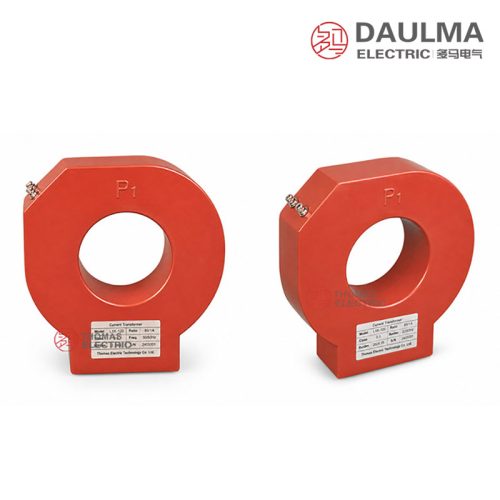
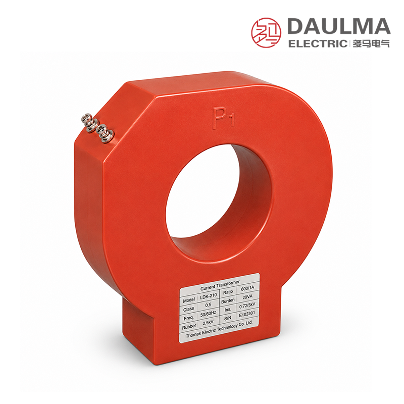
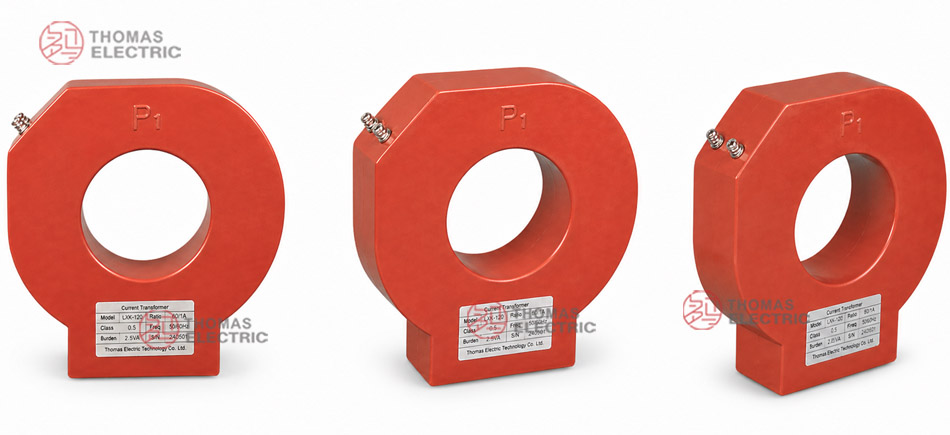
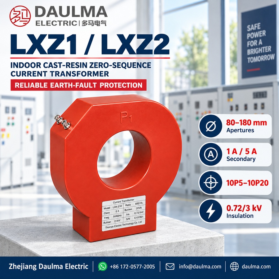
The LXZ1(2)-80/100/120/140/160/180 is an indoor cast-resin zero sequence current transformer designed for AC power systems with a rated insulation level of 0.72/3kV and operating frequency of 50Hz or 60Hz. It features epoxy resin cast insulation, providing high dielectric strength, moisture resistance, and mechanical durability for reliable indoor operation.
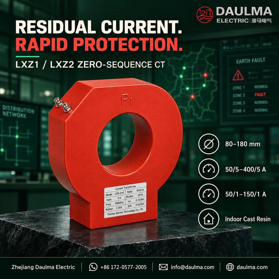
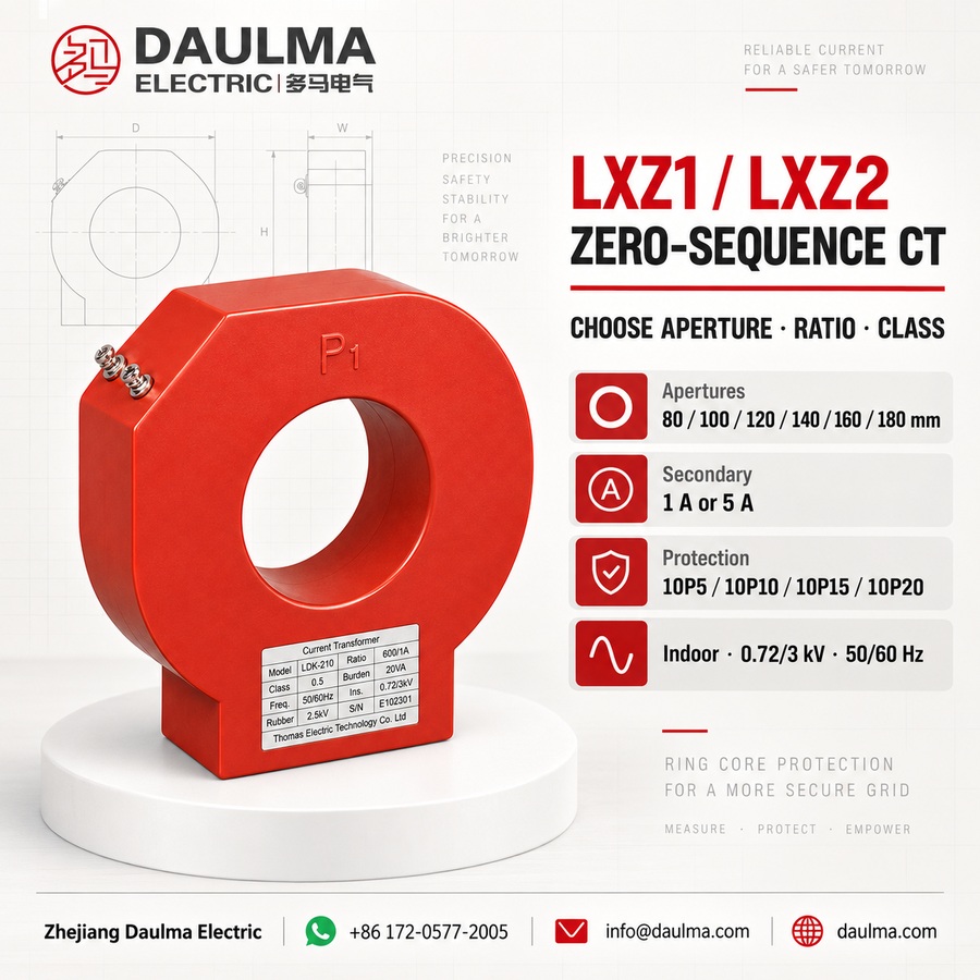
This transformer delivers a standard secondary output of 5A or 1A and offers protection accuracy classes including 10P5, 10P10, 10P15, and 10P20, depending on the selected ratio and burden. It is used for earth fault detection, residual current monitoring, and grounding protection in low-voltage distribution systems, switchgear, and motor or generator feeders, complying with relevant IEC and national standards for protective current transformers.
Key Ratings Snapshot
| Parameter | Rating |
|---|---|
| Rated insulation level | 0.72/3 kV |
| Rated frequency | 50 Hz / 60 Hz |
| Rated secondary current | 1 A or 5 A |
| Protection class | 10P5, 10P10, 10P15, 10P20 |
| System type | Three-phase, four-wire or three-wire |
| Installation environment | Indoor |
| Primary conductor | Three-phase cable group (through-hole) |
| Insulation material | Epoxy cast-resin |
Model Designation
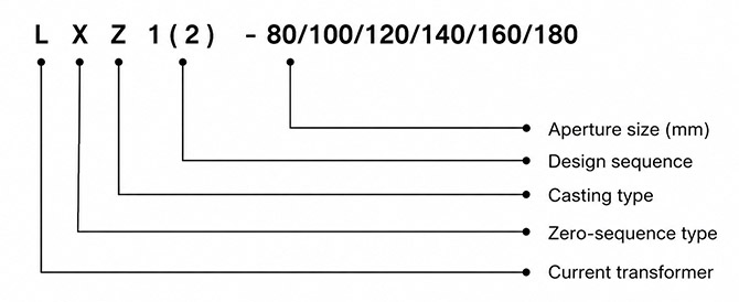
- L: Current transformer
- X: Zero sequence current transformer type
- Z: Cast-resin insulated structure
- 1 / 2: Design structure code
- 80 / 100 / 120 / 140 / 160 / 180: Window diameter or structure size code
Construction
The LXZ1(2) series features a ring-core design with the magnetic core and secondary winding fully encapsulated in epoxy cast-resin insulation. This construction ensures excellent electrical insulation, resistance to humidity and contamination, and robust mechanical support. The through-hole configuration allows the three-phase primary conductors to pass centrally through the window without electrical contact with the transformer. The device is intended for fixed indoor mounting in switchgear panels, protection cabinets, or cable compartments, where it provides reliable zero sequence current sensing for ground fault protection systems.
Technical Parameters
Service Conditions
- Installation location: indoor
- Rated insulation level: 0.72/3kV
- Rated frequency: 50Hz / 60Hz
- Ambient temperature: -25°C to +40°C
- Installation environment: The installation environment should be free from severe vibration, corrosive gas, conductive dust, explosive medium, and heavy pollution.
- Conductor routing: All three phase conductors should pass through the transformer window together in the same direction.
- Mechanical stress: The cable, busbar, or conductor should have sufficient insulation clearance and should not apply mechanical stress to the transformer body.
- Special requirements: For special cable diameter, grounding protection scheme, burden, or protection class requirements, technical confirmation is recommended before ordering.
Technical Parameters
The LXZ1(2)-80/100/120/140/160/180 series are indoor cast-resin zero sequence current transformers rated for 0.72/3kV insulation level, with epoxy resin insulation and an operating temperature range of -25°C to +40°C. They comply with GB 20840.1-2010 and GB 20840.2-2014 standards and support primary current ratios from 50A up to 400A with secondary outputs of 5A or 1A.
| Type | Classes | Rated Current Ratio (A) / Rated Output (VA) | |||||||||||
|---|---|---|---|---|---|---|---|---|---|---|---|---|---|
| 50/5 | 75/5 | 100/5 | 150/5 | 200/5 | 250/5 | 300/5 | 400/5 | 50/1 | 75/1 | 100/1 | 150/1 | ||
| LXZ1-80 LXZ1-100 LXZ1-120 LXZ1-140 LXZ1-160 LXZ1-180 |
10P5 | 5 | 7.5 | 10 | 15 | 20 | 25 | 30 | 40 | 5 | 10 | 10 | 15 |
| 10P10 | 2.5 | 3.75 | 5 | 7.5 | 10 | 15 | 15 | 20 | 2.5 | 3.75 | 5 | 7.5 | |
| 10P15 | 1 | 2 | 2.5 | 3.75 | 5 | 7.5 | 10 | 15 | 2 | 2.5 | 3.75 | 5 | |
| 10P20 | – | 1.5 | 2 | 2.5 | 3.75 | 5 | 7.5 | 10 | 1 | 1.5 | 2 | 3.75 | |
| LXZ2-80 LXZ2-100 LXZ2-120 LXZ2-140 LXZ2-180 |
10P5 | 7.5 | 15 | 20 | 30 | 40 | 50 | 60 | 80 | 10 | 15 | 20 | 30 |
| 10P10 | 3.75 | 5 | 7.5 | 10 | 15 | 20 | 25 | 40 | 5 | 7.5 | 10 | 15 | |
| 10P15 | 2.5 | 3.75 | 5 | 7.5 | 10 | 15 | 15 | 20 | 2.5 | 3.75 | 5 | 7.5 | |
| 10P20 | 1.5 | 2.5 | 3.75 | 5 | 7.5 | 10 | 10 | 15 | 2 | 2.5 | 3.75 | 5 | |
| LXZ2-160 | 10P5 | 7.5 | 10 | 15 | 20 | 30 | 40 | 50 | 60 | 7.5 | 10 | 15 | 25 |
| 10P10 | 3.75 | 5 | 7.5 | 10 | 15 | 20 | 25 | 30 | 3.75 | 5 | 7.5 | 10 | |
| 10P15 | 2 | 2.5 | 3.75 | 5 | 10 | 10 | 15 | 20 | 2.5 | 3.75 | 5 | 7.5 | |
| 10P20 | 1 | 2 | 2.5 | 5 | 5 | 7.5 | 10 | 10 | 2 | 2.5 | 3.75 | 5 | |
Installation & Wiring
Installation Diagram
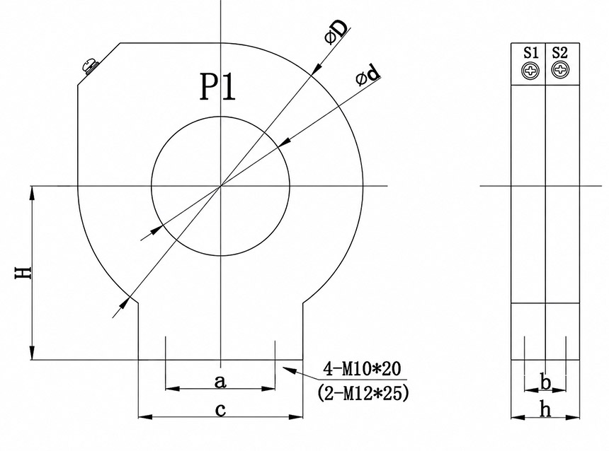
Dimension Reference
| Model | d (mm) |
D (mm) |
H (mm) |
h (mm) |
a (mm) |
b (mm) |
c (mm) |
|---|---|---|---|---|---|---|---|
| LXZ1-80 | 80 | 195 | 130 | 50 | 80 | – | 120 |
| LXZ2-80 | 80 | 195 | 130 | 80 | 80 | 50 | 120 |
| LXZ1-100 | 100 | 215 | 140 | 50 | 80 | – | 120 |
| LXZ2-100 | 100 | 215 | 140 | 80 | 80 | 50 | 120 |
| LXZ1-120 | 120 | 235 | 150 | 50 | 100 | – | 140 |
| LXZ2-120 | 120 | 235 | 150 | 80 | 100 | 50 | 140 |
| LXZ1-140 | 140 | 255 | 160 | 50 | 100 | – | 140 |
| LXZ2-140 | 140 | 255 | 160 | 80 | 100 | 50 | 140 |
| LXZ1-160 | 160 | 265 | 170 | 60 | 100 | – | 140 |
| LXZ2-160 | 160 | 265 | 170 | 80 | 100 | 30 | 140 |
| LXZ1-180 | 180 | 295 | 180 | 50 | 160 | – | 200 |
| LXZ2-180 | 180 | 295 | 180 | 80 | 160 | 50 | 200 |
The LXZ1(2) series zero sequence current transformer features a through-hole ring-core design. Install by passing the three-phase cable, busbar, or conductor group together through the central aperture in the same direction. Mount the unit securely inside an indoor switchgear cabinet or panel according to approved layout drawings, ensuring proper alignment and clearance.
Selection & FAQs
Selection Guide
- Measure the maximum outside diameter of the complete three-phase conductor group and select an 80mm, 100mm, 120mm, 140mm, 160mm or 180mm aperture with adequate installation clearance.
- Compare the LXZ1 and LXZ2 dimensional drawings and mounting heights; the structure selected also affects the available rated output.
- Choose a 1A or 5A secondary and a ratio suited to the expected residual-fault current and the connected relay’s pickup range.
- Specify 10P5, 10P10, 10P15 or 10P20 and verify that the model-specific VA rating covers both relay input and secondary lead burden.
- Confirm indoor service conditions, conductor and screen routing, terminal polarity and a mounting arrangement that imposes no mechanical stress on the cast-resin body.
Frequently Asked Questions
Q1: What does the LXZ1(2) zero-sequence current transformer detect?
It measures the residual current produced by an earth fault so a protection relay can alarm or trip. Typical applications include indoor distribution panels, switchgear and motor or generator feeders.
Q2: What is the difference between LXZ1 and LXZ2?
Both are fixed cast-resin ring-core CTs with the same aperture range, but their mounting dimensions and attainable output differ. Select the structure from the dimensional drawing and the required class, ratio and burden.
Q3: Which aperture sizes and ratios are available?
Apertures are 80mm, 100mm, 120mm, 140mm, 160mm and 180mm. Catalogue ratios cover 50/5A–400/5A or 50/1A–150/1A, subject to the selected model and protection class.
Q4: How should the primary conductors pass through the CT?
All phase conductors of the protected circuit must pass through the same aperture in the same direction. Screen, armour, neutral and PE routing must follow the project’s grounding scheme so normal load current cancels correctly.
Q5: How is the required rated output selected?
Add the protection relay burden to the calculated secondary-cable burden, then choose a model, ratio and accuracy-limit class whose catalogue VA rating is not exceeded. Available output varies substantially by configuration.
Q6: Can the LXZ1(2) be used outdoors?
No. It is intended for fixed indoor installation from −25°C to +40°C in locations without severe vibration, corrosive gas, conductive dust, explosive media or heavy pollution.
Q7: May the secondary circuit be left open while energized?
No. An energized CT with an open secondary can develop hazardous voltage and damage insulation. Qualified personnel should isolate the primary or short the secondary through an approved terminal arrangement before service work.