Overview
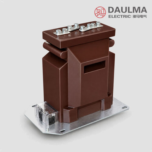
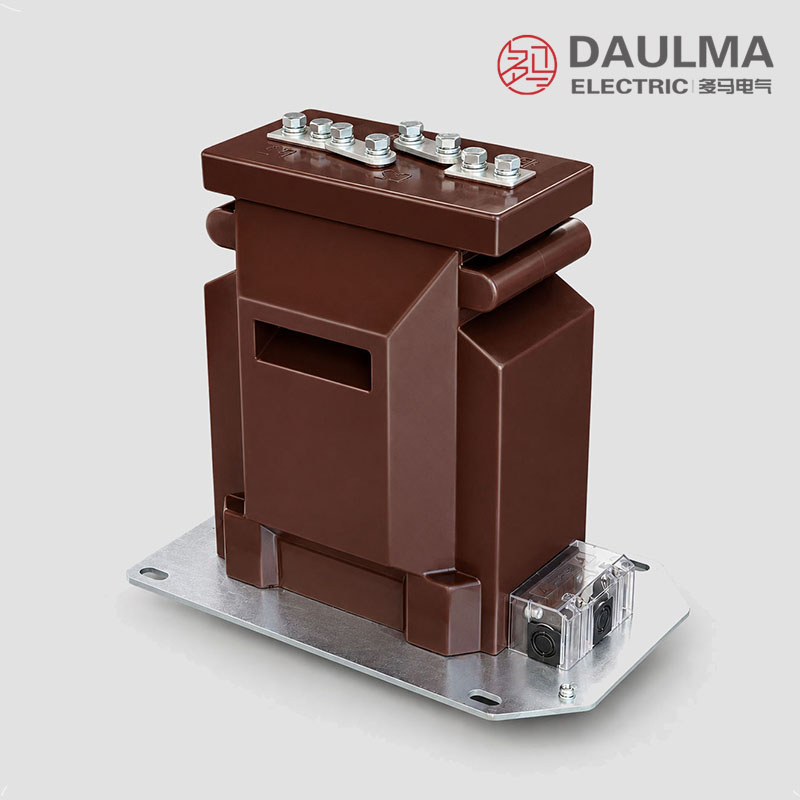
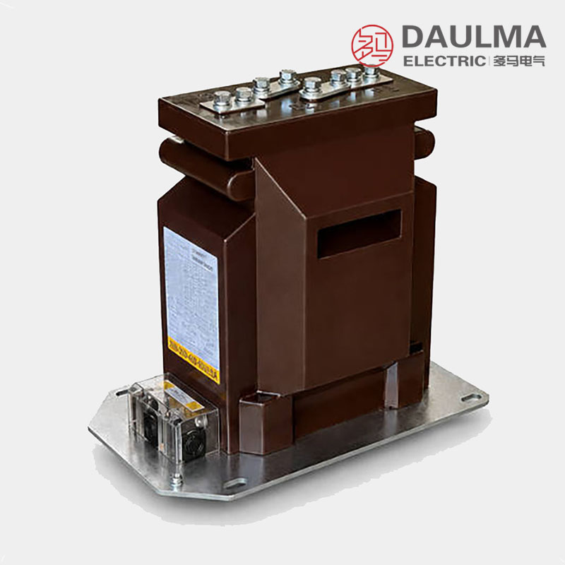
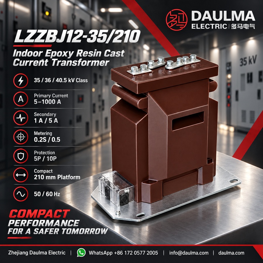
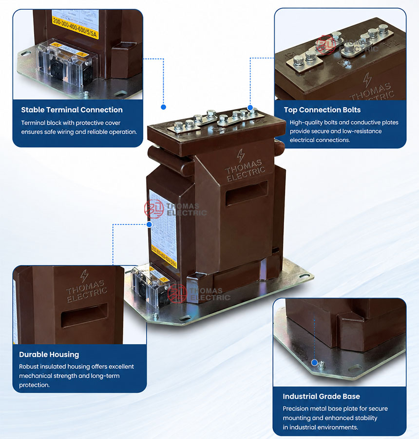
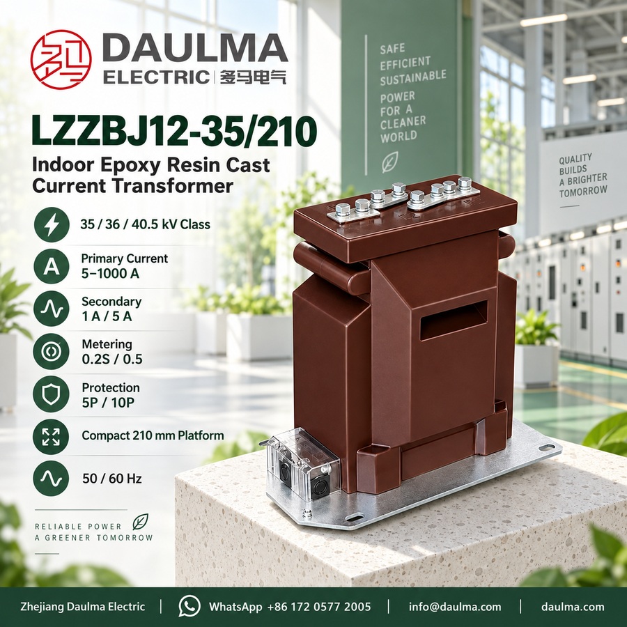
The LZZBJ12-35/210 (ATB-30-210) is an indoor epoxy resin cast current transformer designed for 35kV, 36kV, and 40.5kV medium-voltage AC systems operating at 50Hz or 60Hz. It features a fully enclosed support-type structure with windings and magnetic core sealed in epoxy resin, ensuring high insulation integrity, moisture resistance, and mechanical robustness for indoor switchgear environments.
This CT supports both metering (accuracy classes 0.2S/0.5) and protection (5P/10P) applications, making it suitable for current measurement, energy metering, and relay protection in compact air-insulated switchgear, distribution panels, and metering cabinets. It complies with standard requirements for short-time thermal and dynamic withstand capabilities, and its design aligns with typical project specifications for 35kV-class installations.
Key Ratings Snapshot
| Parameter | Rating |
|---|---|
| System voltage class | 35kV / 36kV / 40.5kV |
| Rated insulation level | 40.5/80/185kV (or 40.5/95/185kV per project) |
| Rated frequency | 50Hz or 60Hz |
| Rated secondary current | 5A or 1A |
| Primary current range | 5A to 1000A (per ratio configuration) |
| Metering accuracy class | 0.2S, 0.5 |
| Protection accuracy class | 5P, 10P |
| Short-time thermal current | 80×I₁ₙ, 100×I₁ₙ, up to 40kA |
| Installation condition | Indoor |
| Insulation material | Epoxy resin cast |
| Structure type | Support-type / pillar-type |
| Secondary terminal location | Side / lower section |
Model Designation
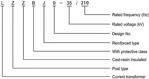
- L: Current transformer.
- Z: Support-type / pillar-type structure.
- Z: Epoxy resin casting insulation.
- B: Series with metering and protection winding options.
- J: Reinforced / protection-capable design reference.
- 12: Compact 35kV indoor CT platform code.
- 35: 35kV-class product for 35kV / 36kV / 40.5kV systems.
- 210: 210mm compact body width platform.
Construction
The LZZBJ12-35/210 features a compact rectangular epoxy resin cast body with a fully enclosed structure that encapsulates the primary conductor, magnetic core, and secondary windings. This construction provides excellent dielectric strength, environmental sealing, and mechanical stability. The primary terminals are located at the top of the unit, while the secondary terminal block is positioned on the side or lower section for convenient access during installation and maintenance within switchgear panels. The 210mm-width design optimizes space usage in compact indoor switchgear compared to wider legacy platforms. Multiple secondary wiring configurations—including single-ratio, dual-ratio, and multi-secondary outputs—are integrated into the terminal arrangement to support flexible application needs for both metering and protection circuits.
Technical Parameters
Service Conditions
- Ambient temperature: -5°C to +40°C
- Installation: Indoor installation for 35kV / 36kV / 40.5kV switchgear and distribution systems.
- Site condition: No severe vibration, shock or mechanical impact at the installation site.
- Air quality: Ambient air should not be seriously polluted by dust, smoke, corrosive gases, vapours or salt.
- Humidity: Indoor service without severe condensation; special requirements should be confirmed by project agreement.
- Maintenance: Keep the epoxy resin surface clean and dry to maintain insulation performance.
- Wiring check: Confirm the correct wiring diagram, ratio connection and terminal marking before energizing.
Technical Parameters
The LZZBJ12-35/210 (ATB-30-210) is an indoor epoxy resin cast current transformer designed for 35kV / 36kV / 40.5kV systems, with a rated primary current range from 5A to 1000A and compliance with IEC 61869 and GB/T 20840 standards. It operates within an ambient temperature of -5°C to +40°C and is suitable for standard indoor environments without severe pollution or condensation.
Data Table 1
| Rated Primary Current (A) |
Accuracy Classes |
Rated Output (VA) | Rated Short-Time Thermal Current (kA) |
Rated Dynamic Current (kA) |
||||
|---|---|---|---|---|---|---|---|---|
| 0.2(S) | 0.5(S) | 10(5)P10 | 5(10)P15 | 5(10)P20 | ||||
| 50 | 0.2(S)/0.5(S) 0.2(S)/10P10 0.5(S)/10P10 0.2(S)/10P15 0.5(S)/10P15 0.2(S)/10P20 0.5(S)/10P20 |
15 | 15 | 15 | 10 | 7.5 | 80*In | 2.5Ith |
| 75 | ||||||||
| 100 | 10/1 | 40 | ||||||
| 150 | 20/1 | 50 | ||||||
| 200 | ||||||||
| 300 | 20/2 | 50 | ||||||
| 400 | ||||||||
| 500 | ||||||||
| 600 | 31.5/2 | 80 | ||||||
| 750 | ||||||||
| 800 | ||||||||
| 1000 | 40/2 | 100 | ||||||
Data Table 2
| Rated Primary Current (A) |
Accuracy Classes |
Rated Output (VA) | Rated Short-Time Thermal Current (kA) |
Rated Dynamic Current (kA) |
||||
|---|---|---|---|---|---|---|---|---|
| 0.2(S) | 0.5(S) | 10(5)P10 | 5(10)P15 | 5(10)P20 | ||||
| 10-20 | 0.2(S)/0.5(S) 0.2(S)/10P10 0.5(S)/10P10 0.2(S)/10P15 0.5(S)/10P15 0.2(S)/10P20 0.5(S)/10P20 |
15 | 15 | 15 | 15 | 10 | 80*In | 2.5Ith |
| 15-30 | ||||||||
| 20-40 | ||||||||
| 30-60 | ||||||||
| 40-80 | ||||||||
| 50-100 | ||||||||
| 100-200 | 100*In | 2.5Ith | ||||||
| 150-200 | ||||||||
| 200-400 | ||||||||
| 250-500 | ||||||||
| 300-600 | ||||||||
Data Table 3
| Rated Primary Current (A) |
Accuracy Classes |
Rated Output (VA) | Rated Short-Time Thermal Current (kA) |
Rated Dynamic Current (kA) |
||||
|---|---|---|---|---|---|---|---|---|
| 0.2(S) | 0.5(S) | 10(5)P10 | 5(10)P15 | 5(10)P20 | ||||
| 10-15-20-30 | 0.2(S)/0.5(S) 0.2(S)/10P10 0.5(S)/10P10 0.2(S)/10P15 0.5(S)/10P15 0.5(S)/10P20 |
10 | 10 | 15 | 10 | 7.5 | 80*In | 2.5Ith |
| 15-20-30-40 | ||||||||
| 20-30-40-60 | ||||||||
| 30-40-60-80 | ||||||||
| 40-75-80-150 | ||||||||
| 50-75-100-150 | ||||||||
| 75-100-150-200 | ||||||||
| 100-150-200-300 | ||||||||
| 150-200-300-400 | ||||||||
Installation & Wiring
Installation Diagram
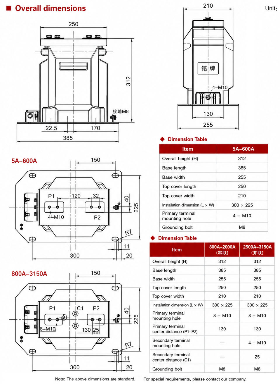
The LZZBJ12-35/210 current transformer is installed vertically within indoor switchgear, secured via the bottom mounting base. Ensure adequate clearance around the unit for primary conductor routing, secondary wiring access, and compliance with 40.5kV electrical clearance requirements. Terminal access must be maintained on both front and side faces as per the approved project drawing.
Selection & FAQs
Selection Guide
- Select the 210 platform from switchgear space and clearance constraints. Confirm actual width, height, primary-terminal spacing, base pattern, secondary access and 40.5kV clearances on the approved outline.
- Choose single, double or combined ratio deliberately. The family spans 5A–1000A, with combined groups described from 10A upward; require a terminal diagram and guaranteed performance at each ratio.
- Calculate burden before choosing the compact design. Published outputs are 5VA–15VA, so include relay or meter input, cable resistance, test block and terminals for every core.
- Match the full accuracy combination. Options include 0.2S/0.5, measurement with 10P10, 10P15 or 10P20, plus selected 5P classes; obtain a per-core VA and terminal schedule.
- Resolve insulation and fault requirements. Specify either 40.5/80/185kV or the project-required 40.5/95/185kV, then confirm short-time duration, peak current, partial discharge, altitude and IEC 61869 tests.
Frequently Asked Questions
Q1: Can this 35kV current transformer be used on 36kV systems?
Yes, it is designed for 35kV, 36kV, and 40.5kV indoor distribution systems. The epoxy resin cast insulation ensures reliable performance across these voltage levels. Confirm exact system parameters with our engineering team.
Q2: What are the ambient temperature limits for indoor installation?
The LZZBJ12-35/210 operates within an ambient temperature range of -5°C to +40°C. Ensure the installation site has no severe condensation or corrosive gases. Contact us for special environmental requirements.
Q3: Which primary current ratings are available for this model?
Rated primary currents range from 5A to 1000A. It complies with IEC 61869 and GB/T 20840 standards for accurate current measurement. Specify your required ratio and accuracy class during inquiry.
Q4: What factory tests are performed before shipment?
All units undergo standard routine tests per IEC 61869 and GB/T 20840. Specific type tests or third-party certifications are subject to project confirmation. Please contact our sales team for detailed test reports.
Q5: How long is the delivery time for custom ratios?
Standard models ship quickly, but custom ratio configurations are subject to production scheduling. Delivery times depend on order quantity and specific technical requirements. Contact us with your exact specifications for a precise lead time.
Q6: Where is this epoxy resin cast current transformer applied?
It is specifically designed for indoor 35kV to 40.5kV switchgear and distribution systems. The epoxy casting provides high insulation performance in clean, non-polluted environments. Verify site conditions match our service specifications.
Q7: How should the CT be maintained after installation?
Keep the epoxy resin surface clean and dry to maintain optimal insulation performance. Always confirm the correct wiring diagram and terminal markings before energizing. Contact our support team for detailed maintenance guidelines.