Overview
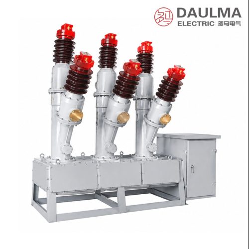
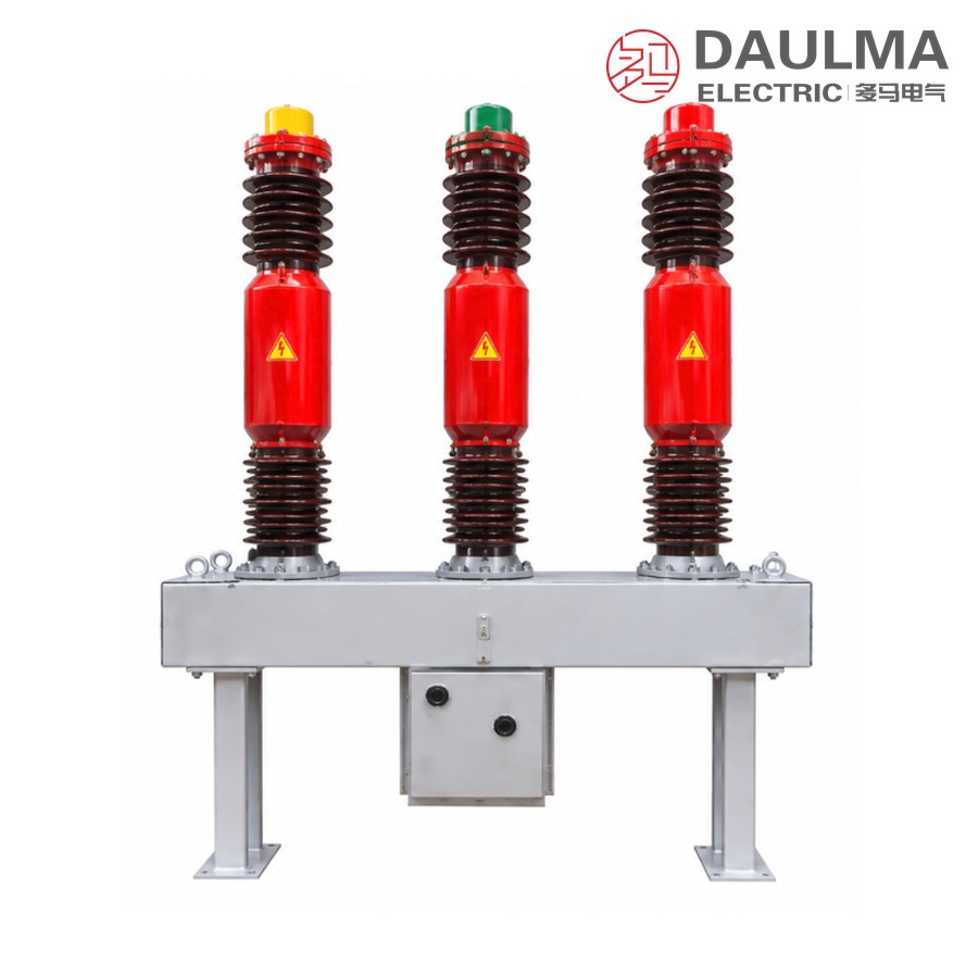
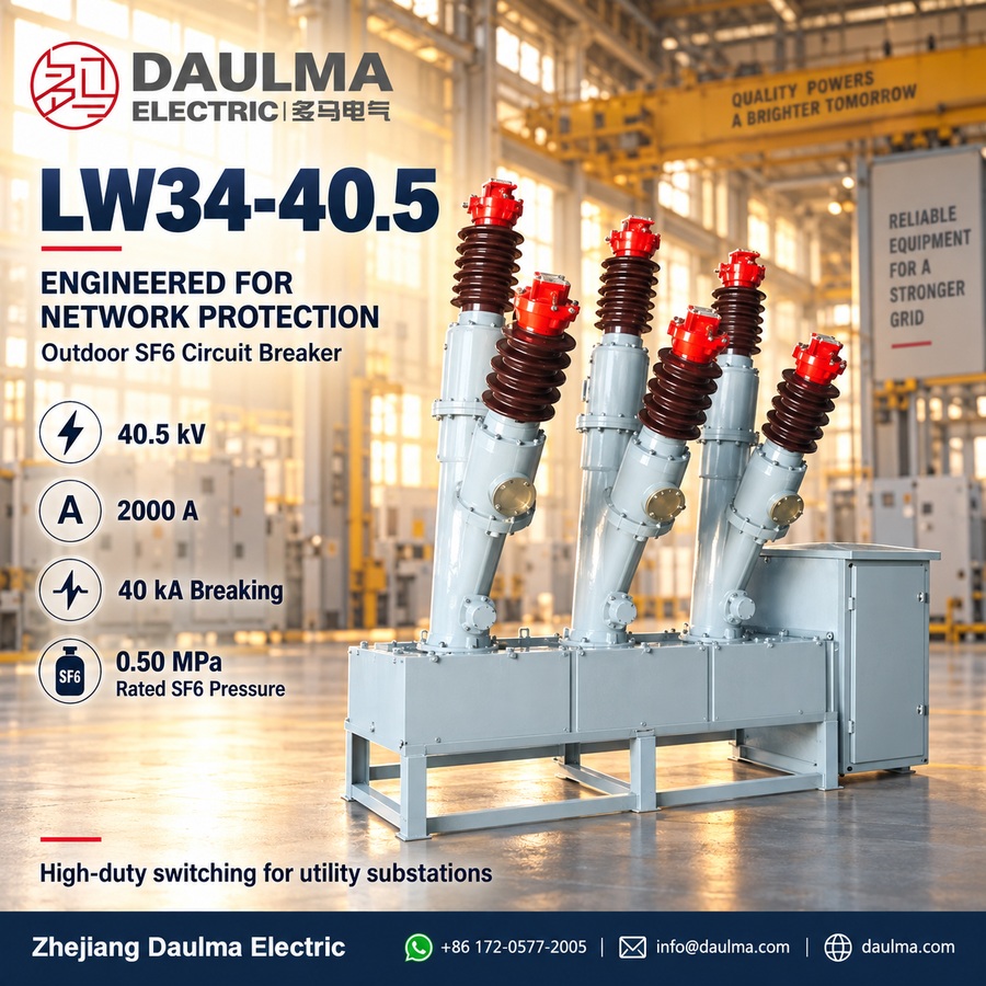
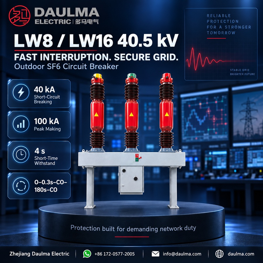
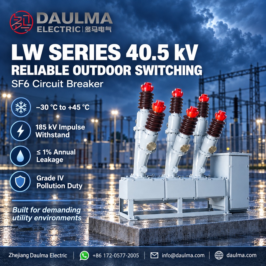
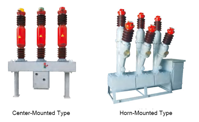
The LW8, LW16, LW34-40.5, and T2000-40 series are outdoor high-voltage AC SF6 circuit breakers designed for three-phase 50Hz systems with a rated voltage of 40.5kV. These breakers provide reliable control and protection for 40.5kV transmission networks and are well-suited for combined breaker and capacitor bank installations. They deliver exceptional performance in urban, industrial, rural, and substation applications.
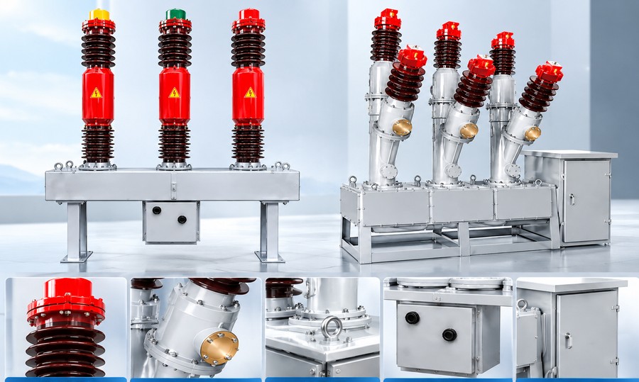
Featuring a compact ceramic column structure integrated with the CT14 spring-operated mechanism, these breakers offer excellent mechanical reliability with over 3,000 operational cycles. They utilize advanced air-compression arc-extinguishing technology, enabling up to 12 consecutive breaks at 40kA without maintenance. High-precision current transformers (up to 12 units) support long-distance load lines, while superior sealing ensures an annual SF6 leakage rate below 1%.
Key Ratings Snapshot
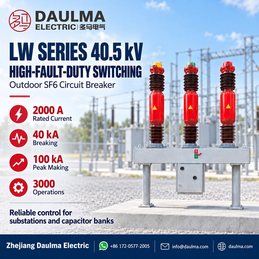
| Parameter | Value |
|---|---|
| Rated Voltage | 40.5 kV |
| Rated Current | 2000 A |
| Rated Short-Circuit Breaking Current | 40 kA |
| Rated Short-Circuit Closing Current (Peak) | 100 kA |
| Lightning Impulse Withstand Voltage | 185 kV |
| Power Frequency Withstand Voltage (1 min) | 95 kV |
| Mechanical Life | 3000 operations |
| SF6 Rated Pressure (20 degC) | 0.50 MPa |
| Annual SF6 Leakage Rate | <=1% |
| Rated Capacitor Switching Current | 400 A |
Model Designation
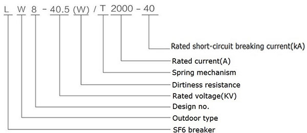
- L: SF6 circuit breaker
- W: Outdoor installation
- 8/16/34: Design sequence number
- 40.5: Rated voltage (kV)
- (W): Pollution-resistant variant (optional)
- T: Spring-operated mechanism
- 2000: Rated current (A)
- 40: Rated short-circuit breaking current (kA)
Construction
The breaker features a vacuum-sealed SF6 chamber with imported “V”-type dynamic seals incorporating spring pressure compensation to maintain stable gas integrity. Terminal markings follow standard conventions: P1/P2 for primary power terminals and S1/S2 for secondary current transformer outputs. Built-in micro-crystalline alloy current transformers achieve accuracy classes of 0.2 or 0.2S. The unit includes an MKZ-type SF6 density monitor that provides temperature-compensated pressure readings for simplified maintenance.
Safety Warning: Always verify de-energization and ground the system before inspection or maintenance. Do not operate if SF6 pressure falls below the minimum functional level (0.45 MPa at 20 degC).
Technical Parameters
Service Conditions
- Altitude: <=3000m
- Ambient Temperature: -30 degC to +45 degC
- Pollution Level: <=Grade IV per GB/T5582
- Relative Humidity: Daily <=95%, monthly average <=90% (at 25 degC)
- Wind Pressure: <=700Pa (equivalent to 34 m/s wind speed)
- Daily Temperature Variation: <=25 degC
- Sunlight Intensity: <=0.1W/cm2
- Seismic Resistance: Horizontal acceleration <=0.2g, vertical <=0.1g
- Ice Coating Thickness: <=10mm
- Installation Environment: Outdoor only
Technical Data
| Item | Unit | Data |
|---|---|---|
| Rated Voltage | kV | 40.5 |
| Rated Insulation Level Lightning Impulse Withstand Voltage (Peak) |
kV | 185 |
| Rated Insulation Level 1min Power Frequency Withstand Voltage |
kV | 95 |
| Rated Current | A | 2000 |
| Mechanical Life | Times | 3000 |
| SF6 Gas Rated Pressure (20 degC Gauge Pressure) | MPa | 0.50 |
| Alarm Pressure / Minimum Functional Pressure (20 degC Gauge Pressure) | MPa | 0.47 / 0.45 |
| Rated Short-Circuit Breaking Current | kA | 40 |
| Rated Short-Circuit Closing Current (Peak) | kA | 100 |
| Rated Short-Time Withstand Current (Thermal Stability Current) | kA | 40 |
| Rated Peak Withstand Current (Dynamic Stability Current) | kA | 100 |
| Accumulated Breaking Times at Rated Short-Circuit Current | Times | 12 |
| Rated Short-Time Duration | s | 4 |
| Closing Time (At Rated Operating Voltage) | s | <=0.1 |
| Opening Time (At Rated Operating Voltage) | s | <=0.6 |
| Rated Operating Sequence | 0-0.3s-CO-180s-CO | |
| Rated Capacitor Switching Current | A | 400 |
| Annual Leakage Rate | % | <=1 |
| SF6 Gas Moisture Content (V/V) | <=150×10^-6 | |
| Rated Operating Voltage with CT14 Spring Mechanism | V | AC: 220, 380; DC: 48, 110, 220 |
| Energy Storage Motor Voltage | V | AC: 220, 380; DC: 110, 220 |
| SF6 Gas Weight | kg | 8 |
| Breaker Weight (Including Mechanism) | kg | 1400 |
| Moving Contact Stroke | mm | 95 +/- 2 |
| Contact Opening Distance | mm | 60 +/- 1.5 |
| Closing Synchronization | ms | <=2 |
| Opening Synchronization | ms | <=3 |
| Main Circuit Resistance | mOhm | <=120 |
| Closing Speed | m/s | 3.2 +/- 0.2 |
| Opening Speed | m/s | 3.4 +/- 0.2 |
| Closing Buffer Stroke | mm | 10 |
| Closing Buffer Gap | mm | 1 ~ 2 |
| Partial Discharge 48.6kV | pC | 20 |
| Discharge 28kV | pC | 10 |
| Rated Motor Current (A) | A | 5 |
| Normal Operating Voltage Range | 85% ~ 110% of Rated Operating Voltage | |
| Energy Storage Time Under Rated Voltage | s | Less than 15 |
Installation & Wiring
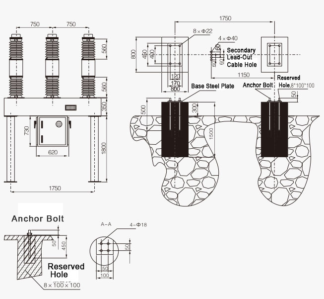
Installation Diagram
Mount the breaker on a level concrete foundation using the base frame (item 7). Ensure adequate clearance around the unit for maintenance and gas handling. All electrical connections must comply with local codes and use torque specifications provided in the installation manual.
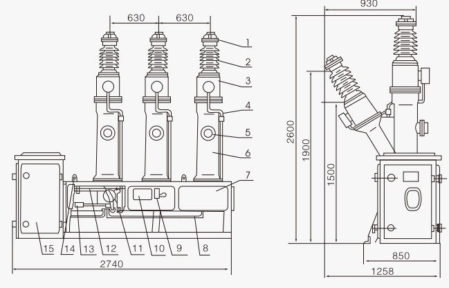
Outline Dimensions
| Dimension | Value (mm) |
|---|---|
| 1. Outlet Cap | – |
| 2. Bushing | – |
| 3. Current Transformer | – |
| 4. CT Connection Protective Tube | – |
| 5. Pole Attachment | – |
| 6. Enclosure | – |
| 7. Base Frame | – |
| 8. Gas Pipeline | – |
| 9. Open/Close Indicator | – |
| 10. Nameplate | – |
| 11. Transmission Box | – |
| 12. Trip Spring | – |
Selection & FAQs
Selection Guide
- Confirm a 40.5kV, 50Hz outdoor system and verify the 2000A continuous, 40kA breaking, 100kA making and four-second withstand ratings against network studies.
- Select LW8, LW16, LW34-40.5 or the applicable variant only after comparing structure, mechanism, pollution duty, CT arrangement and dimensional drawings.
- Specify CT14 control and charging-motor voltages from the available AC/DC options and coordinate trip/close coils, protection, reclosing and remote indication.
- Define the required built-in CT quantity, ratio, core function, 0.2/0.2S metering class where applicable, burden and terminal arrangement.
- Check −30°C to +45°C outdoor conditions, foundation loading for the 1400kg assembly, clearances, grounding and provision for compliant SF₆ handling.
Frequently Asked Questions
Q1: Can this 40.5kV SF6 circuit breaker operate at high altitudes?
Yes, it supports altitudes up to 3000m. For installations above this limit, derating or custom insulation design is required. Please contact us for site-specific adjustments.
Q2: What are the seismic and temperature limits for outdoor installation?
The breaker withstands horizontal acceleration up to 0.2g and ambient temperatures from -30°C to +45°C. Verify local seismic requirements with our engineering team before ordering.
Q3: Which SF6 gas pressure rating is required for normal operation?
The rated SF6 gauge pressure is 0.50 MPa at 20°C. Minimum function and alarm pressure values are subject to confirmation. Request the full datasheet for exact gas monitoring parameters.
Q4: What routine factory tests are performed before shipment?
Standard routine tests include mechanical operations, SF6 gas leak detection, and power frequency withstand voltage tests. Specific type test certificates are subject to confirmation upon request.
Q5: How many mechanical operations can this breaker guarantee?
It guarantees a mechanical life of 3000 operations under standard conditions. Customization for higher operation cycles is subject to confirmation. Contact sales for detailed delivery and customization options.
Q6: Where are these LW series outdoor circuit breakers typically applied?
They are designed for 40.5kV outdoor high-voltage AC power systems, protecting substations and industrial grids. They are suitable for Grade IV pollution levels per GB/T5582. Confirm specific environmental conditions with our engineers.
Q7: What is the lightning impulse withstand voltage for this model?
The rated lightning impulse withstand voltage peak is 185kV, with a 1-minute power frequency withstand of 95kV. Confirm specific insulation coordination requirements with our technical team.