Overview
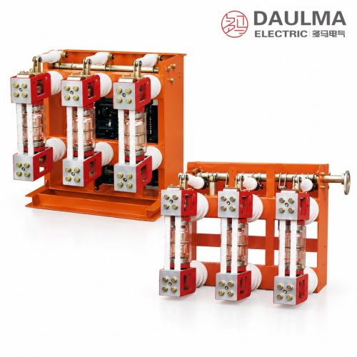
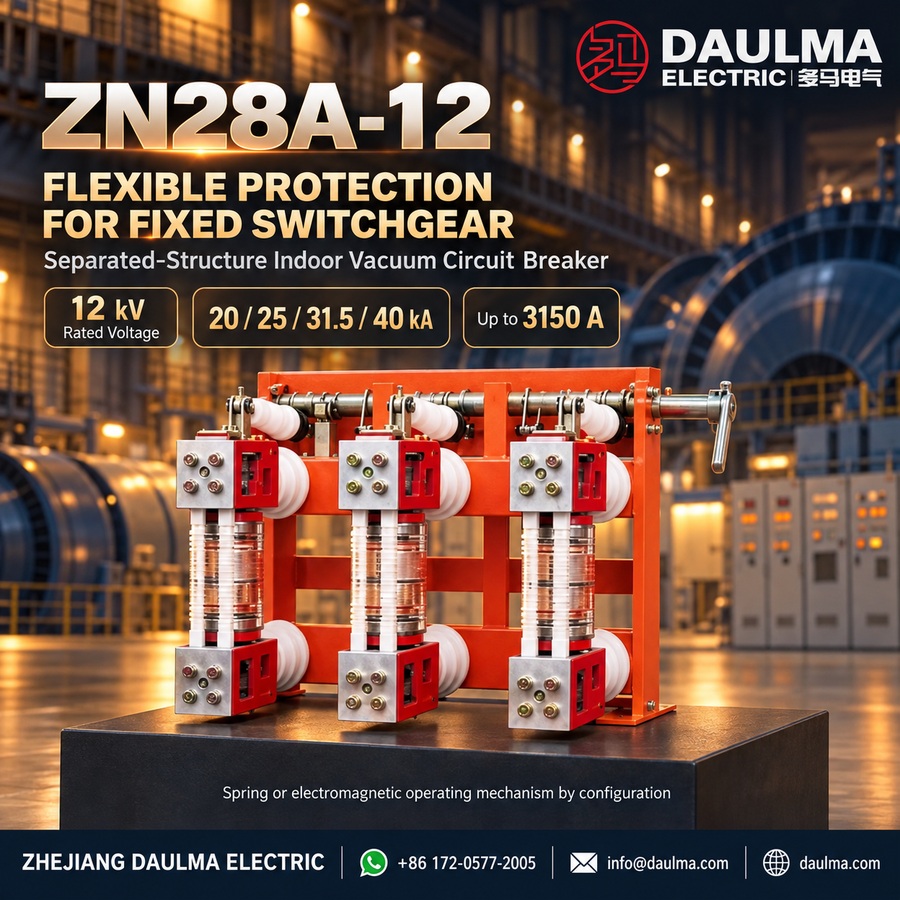
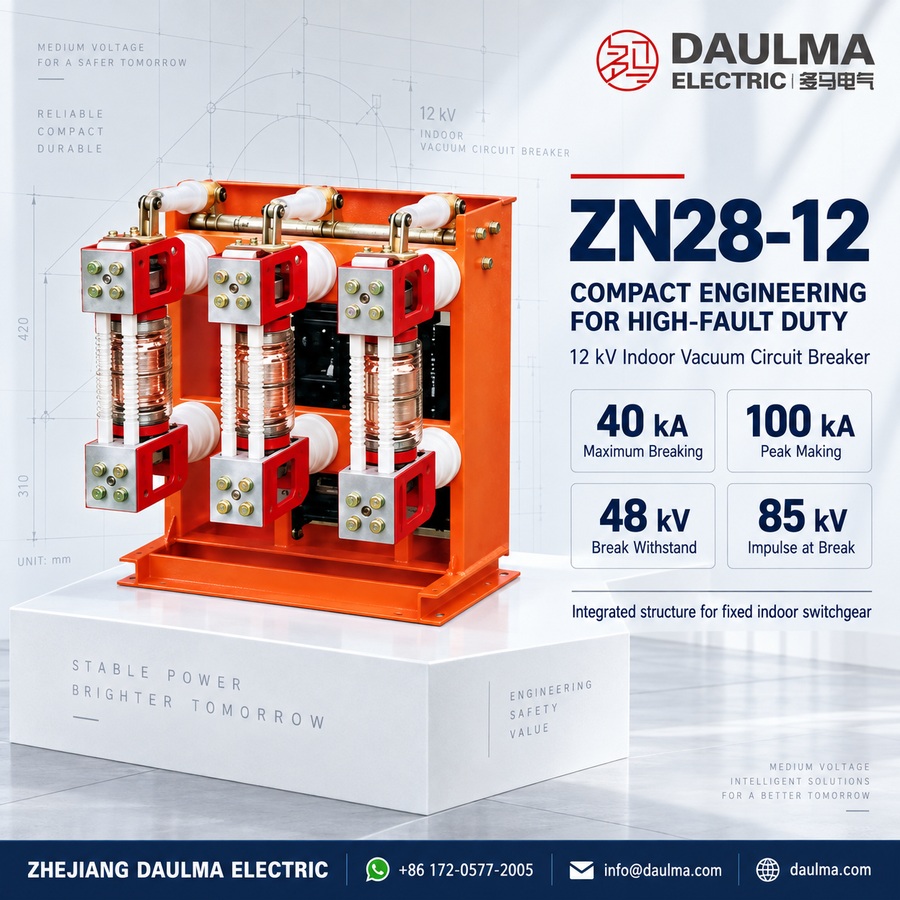
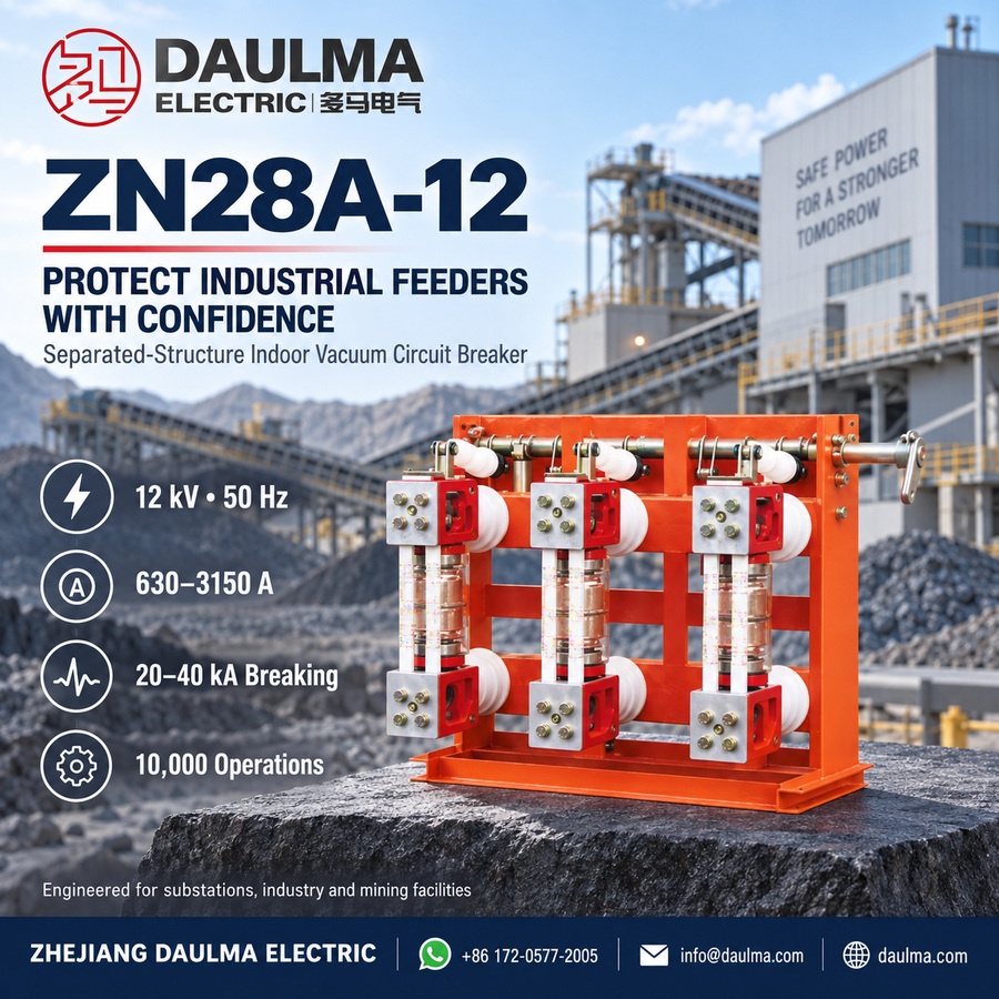
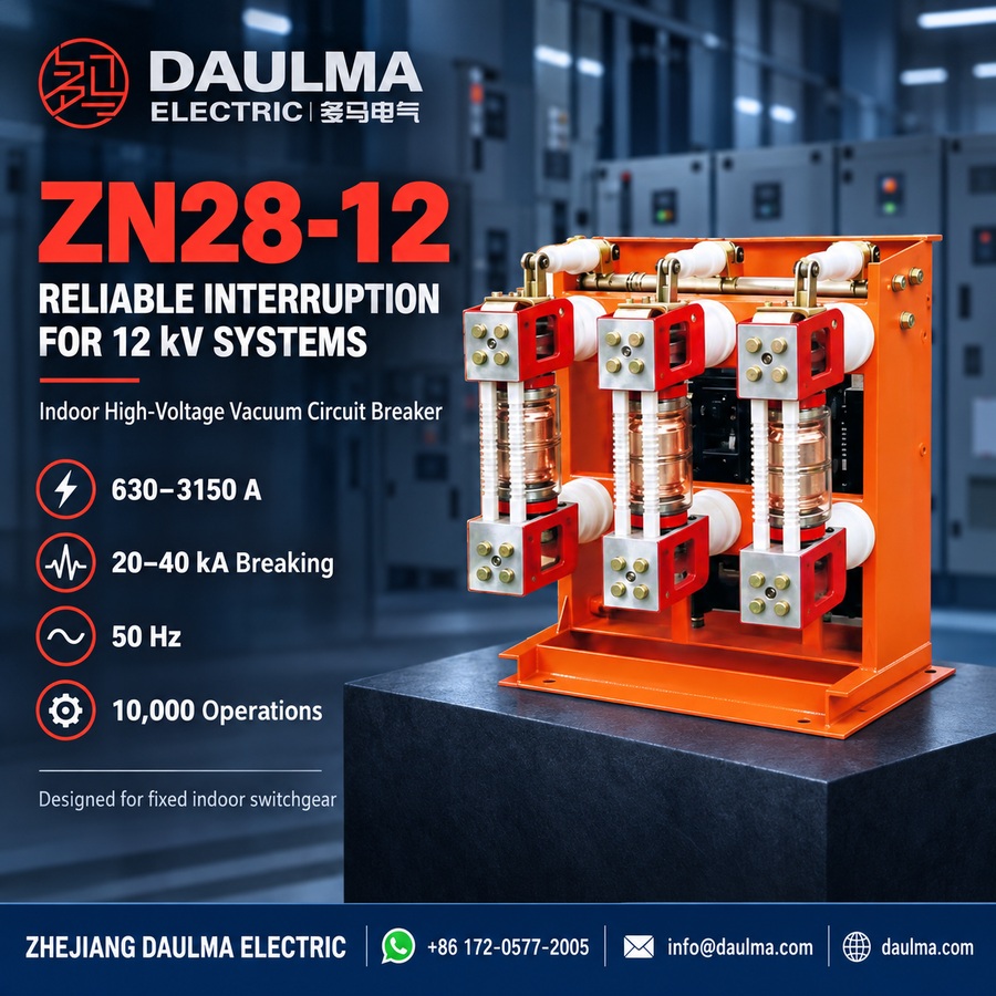
The ZN28-12 series is an indoor, three-phase AC 50Hz high-voltage vacuum circuit breaker rated at 12kV, engineered for reliable operation in fixed switchgear installations. Compliant with GB1984-89 standards, it supports both integrated (ZN28-12) and separated (ZN28A-12) structural configurations, making it ideal for use in industrial power systems, substations, and mining facilities requiring frequent switching and robust fault protection.
Built for durability and precision, the ZN28-12 features a self-contained operating mechanismâcompatible with CT17/CT19 spring-charged or CD17/CD10A electromagnetic typesâensuring stable mechanical performance. The main shaft rotates precisely at 58 deg +/- 1 deg via a connecting rod, while critical components like the opening spring and oil buffer are securely enclosed within the frame. Pre-drilled mounting holes simplify installation, and the design meets all specified technical and safety parameters.
Key Ratings Snapshot
| Parameter | Value |
|---|---|
| Rated Voltage | 12 kV |
| Rated Current | 630:1000:1250:1600:2000:2500:3150 A |
| Rated Short-Circuit Breaking Current | 20:25:31.5:40 kA |
| Rated Short-Circuit Closing Current (Peak) | 50:63:80:100 kA |
| 4s Short-Time Withstand Current | 20:25:31.5:40 kA |
| Power Frequency Withstand Voltage (Break) | 48 kV |
| Impulse Withstand Voltage (Break) | 85 kV |
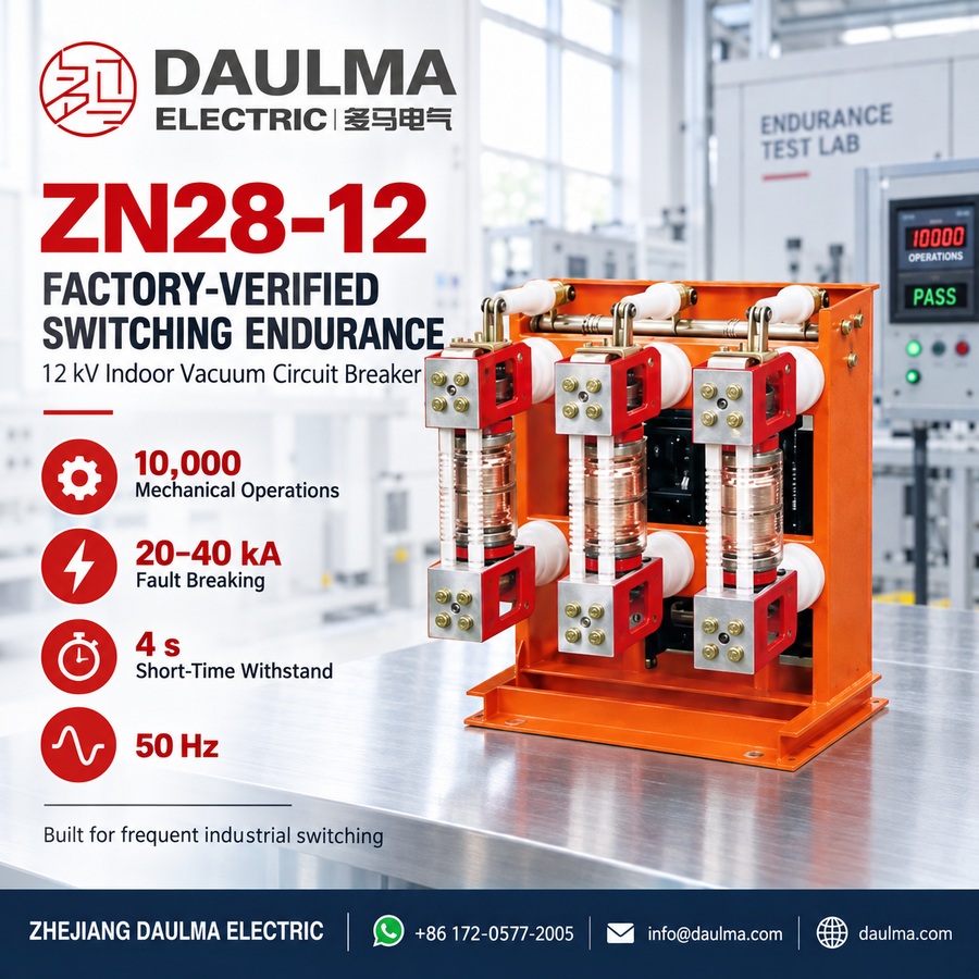
| Mechanical Life | 10,000 operations |
| Contact Opening Distance | 11 +/- 1 mm |
| Main Circuit Resistance | <=50 muOhm |
Model Designation
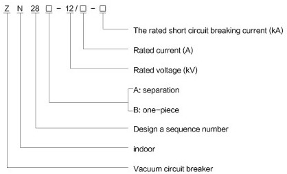
- Z: Vacuum circuit breaker.
- N: Indoor type.
- 28: Design sequence number.
- 12: Rated voltage (kV).
- A: Separated structure; B: One-piece (integrated) structure.
- â¡: Rated current (A).
- â¡: Rated short-circuit breaking current (kA).
Construction
The breaker employs a sealed longitudinal magnetic field vacuum arc extinguishing chamber for superior arc interruption. Its frame houses six rear-mounted insulators: three upper ones secure the moving bracket, and three lower ones hold the static bracket. The rear ends of these brackets serve as primary outlet terminals (P1/P2). The vacuum interrupter is mounted between the brackets and linked to the main shaft through an insulating rod and swing arm. Two additional insulating rods connect the brackets, forming a rigid, unified structure that enhances mechanical strength and stability.
Safety Note: Always de-energize and ground the system before handling terminals or performing maintenance.
Technical Parameters
Service Conditions
- Ambient Temperature: -10 deg to +40 deg.
- Altitude: <=1000m.
- Humidity: Daily relative humidity <=95%; Monthly relative humidity <=90%; Daily water vapor pressure <=2.2kPa, monthly <=1.8kPa.
- Air Quality: Free from dust, smoke, corrosive or combustible gases, vapors, or salt spray.
- Vibration: Minimal external vibrations or ground motion.
- Electromagnetic Interference: Induced voltage in the secondary system <=1.6kV.
Technical Data
| Item | Unit | 20kA | 25kA | 31.5kA | 40kA |
|---|---|---|---|---|---|
| Rated Voltage | kV | 12 | |||
| Rated Current | A | 630 1000 1250 |
1250 1600 |
1250:1600 2000:2500 |
1600 2500 3150 |
| Rated Short-Circuit Breaking Current | kA | 20 | 25 | 31.5 | 40 |
| Rated Short-Circuit Closing Current (Peak) | kA | 50 | 63 | 80 | 100 |
| Rated Peak Withstand Current | kA | 50 | 63 | 80 | 100 |
| 4s Rated Short-Time Withstand Current | kA | 20 | 25 | 31.5 | 40 |
| Rated Insulation Level Power Frequency Withstand Voltage (After Breaking) |
kV | 42 (Break 48) | |||
| Rated Insulation Level Impulse Withstand Voltage (After Breaking) |
kV | 75 (Break 85) | |||
| Rated Operating Sequence | Open:0.3s:Close Open:180s:Close | ||||
| Mechanical Life | Times | 10,000 | |||
| Rated Short-Circuit Current Breaking Times | Times | 30 | 30 | 30 | 20 |
| Operating Mechanism Voltage Rated Operating Voltage |
V | 110:220 | 110:220 | 220 | 220 |
| Operating Mechanism Voltage Rated Closing Current |
A | 71 | 71 | 71 | 128 |
| Operating Mechanism Voltage Rated Opening Voltage |
V | AC/DC 110:220 | |||
| Operating Mechanism Voltage Rated Opening Current |
A | 3.0 | |||
| Contact Opening Distance | mm | 11 +/- 1 | |||
| Overtravel (Contact Spring Compression Length) | mm | 4 +/- 1 | |||
| Three-Phase Closing Non-Synchronism | ms | <=2 | |||
| Contact Closing Bounce Time | ms | <=2 | |||
| Average Opening Speed (Pole 6mm) | m/s | 1.2 +/- 0.3 | |||
| Average Closing Speed | m/s | 0.6 +/- 0.2 | |||
| Opening Time Maximum Operating Voltage |
s | <=0.06 | |||
| Opening Time Minimum Operating Voltage |
s | <=0.08 | |||
| Closing Time | s | <=0.1 | |||
| Main Circuit Resistance | muOhm | <=50 | |||
| Cumulative Contact Wear Allowance | mm | 3 | |||
| Oil Buffer Stroke | mm | 10 | |||
Installation & Wiring
Installation Diagram
Mounting requires secure fixation to pre-drilled base holes in fixed switchgear cabinets such as GG-1A(Z) or XGN2A10(Z). Ensure proper alignment of primary terminals (P1/P2) and maintain safe clearances per local electrical codes.
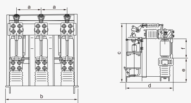

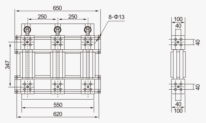
Outline Dimensions
| Dimension | Value (mm) |
|---|---|
| a | 230 (for 20kA:25kA:31.5kA); 275 +/- 1 (for 40kA) |
| b | 600 (for 20kA:25kA:31.5kA); 690 (for 40kA) |
| c | 707 (for 20kA:25kA:31.5kA); 842 (for 40kA) |
| d | 560 (for 20kA:25kA:31.5kA); 652 (for 40kA) |
| e | 293-20 (for 20kA:25kA:31.5kA); 342-20 (for 40kA) |
| f | 227 +/- 1 (all ratings) |
Selection & FAQs
Selection Guide
- Confirm a 12kV, 50Hz fixed-switchgear application and choose rated current from 630A to 3150A after load, temperature-rise and enclosure checks.
- Select 20kA, 25kA, 31.5kA or 40kA breaking capacity above the calculated fault current, with matching four-second and peak withstand ratings.
- Choose the ZN28 integrated or ZN28A separated structure according to cabinet layout, mechanism location, linkage and maintenance access.
- Specify CT17/CT19 spring or CD17/CD10A electromagnetic operation and ensure the AC/DC 110V or 220V trip/close supply matches the exact rating.
- Verify GG-1A(Z), XGN2A-10(Z) or other cabinet dimensions, P1/P2 alignment, clearances, interlocks, grounding and mounting holes from approved drawings.
Frequently Asked Questions
Q1: What is the maximum installation altitude for this 12kV vacuum circuit breaker?
The maximum rated altitude is 1000m. For higher altitudes, derating factors apply. Please contact our engineering team for altitude-specific technical confirmation.
Q2: Which short-circuit breaking current ratings are available for the ZN28-12 model?
Available ratings include 20kA, 25kA, 31.5kA, and 40kA. Select the rating based on your system’s maximum fault level. Specify your exact requirement during order placement.
Q3: Can this indoor high-voltage circuit breaker operate in high humidity conditions?
Yes, provided daily relative humidity remains ≤95% and monthly ≤90%. Ensure the switchgear room has adequate ventilation to prevent condensation.
Q4: What maximum rated currents are supported for the 40kA short-circuit model?
The 40kA model supports rated currents of 1600A, 2500A, and 3150A. Confirm your specific current requirement with our sales team before finalizing the order.
Q5: How are routine factory tests documented before shipment?
Standard routine tests include mechanical operations, main circuit resistance, and high-voltage withstand tests. Detailed test reports are provided upon request.
Q6: Is the ZN28-12 suitable for indoor medium-voltage switchgear applications?
Yes, it is specifically designed for 12kV indoor AC power systems. It is ideal for industrial and mining enterprises, power plants, and substations.
Q7: Are there specific ambient air quality requirements for installing this breaker?
The installation environment must be free from dust, smoke, corrosive gases, and salt spray. Ensure minimal external vibrations during operation.