Overview
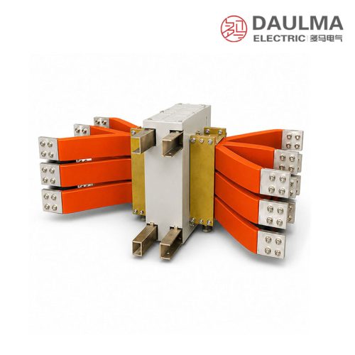
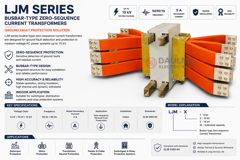
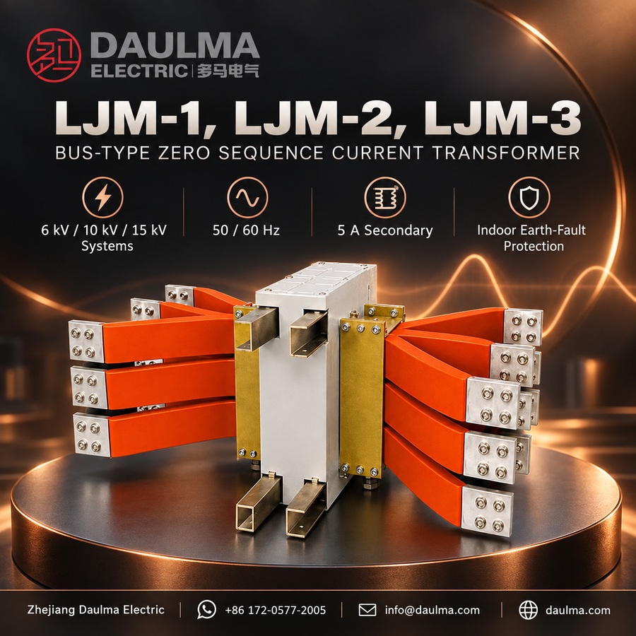
The LJM-1, LJM-2, LJM-3 series busbar-type zero-sequence current transformers are precision electromagnetic devices engineered for reliable ground fault protection in medium-voltage AC power systems. Designed for indoor use in 6 kV, 10 kV, and 15 kV networks, these transformers detect residual (zero-sequence) current during single line-to-ground faults in generators, motors, and distribution feeders.
Operating at standard frequencies of 50 Hz or 60 Hz, the LJM series features an integrated busbar-type structure that simplifies installation by allowing three-phase cables to pass directly through the core without external primary connections, ensuring robust performance and long-term reliability in switchgear environments.
Key Ratings Snapshot
| Parameter | Value |
|---|---|
| System voltage class | 6 kV, 10 kV, 15 kV |
| Rated frequency | 50 Hz or 60 Hz |
| Rated secondary current | 5 A |
| Application type | Zero-sequence protection (ground fault detection) |
| Primary conductor | Integrated busbar-type (cable-through design) |
| Thermal withstand | High, suitable for MV applications |
| Dynamic withstand | Robust for system fault conditions |
| Installation environment | Indoor only |
| Secondary terminals | K1 / K2 |
| Recommended relay | DD11/60 |
Model Designation
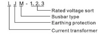
- L: Current transformer (CT)
- J: Ground protection application (zero-sequence detection)
- M: Busbar-type structure (cable-through design)
- 1 / 2 / 3: Voltage class code and current rating designation
- 3L: Extended rating variant (higher primary current capacity)
Construction
The LJM series employs a busbar-type configuration with an integrated primary conductor path, enabling direct cable-through installation. This eliminates the need for discrete primary terminals, reducing complexity and enhancing reliability. The ring-type magnetic core is optimized specifically for zero-sequence current detection, ensuring accurate response during ground fault events.
Voltage class-specific insulation systems protect internal components, while secondary terminals (K1/K2) provide secure connection points for protective relays. The robust mechanical design ensures stable operation in typical indoor industrial switchgear environments, with adequate clearance for heat dissipation and maintenance access.
Technical Parameters
Service Conditions
- Installation environment: Indoor only in clean, non-corrosive atmosphere
- Altitude: Standard range; engineering confirmation required for >1000 m
- Ambient temperature: -5 deg to +40 deg C
- Relative humidity: <=95% at 25 deg C
- Environmental restrictions: No corrosive gases, conductive dust, explosive vapors, or severe vibration
Technical Data
| Model | System Voltage (kV) |
Frequency (Hz) |
Secondary Current (A) |
Primary Type |
|---|---|---|---|---|
| LJM-1 | 6 | 50/60 | 5 | Busbar-type |
| LJM-2 | 10 | 50/60 | 5 | Busbar-type |
| LJM-3 | 15 | 50/60 | 5 | Busbar-type |
| LJM-3L | 15 | 50/60 | 5 | Busbar-type (extended capacity) |
Installation & Wiring
Installation Diagram
Install the LJM transformer in indoor switchgear or motor control centers with adequate ventilation. Pass all three-phase cables or busbars through the central aperture in correct phase sequence to ensure proper zero-sequence flux summation. Connect secondary terminals K1 and K2 to the zero-sequence relay using appropriate gauge wiring, observing polarity for correct relay operation.
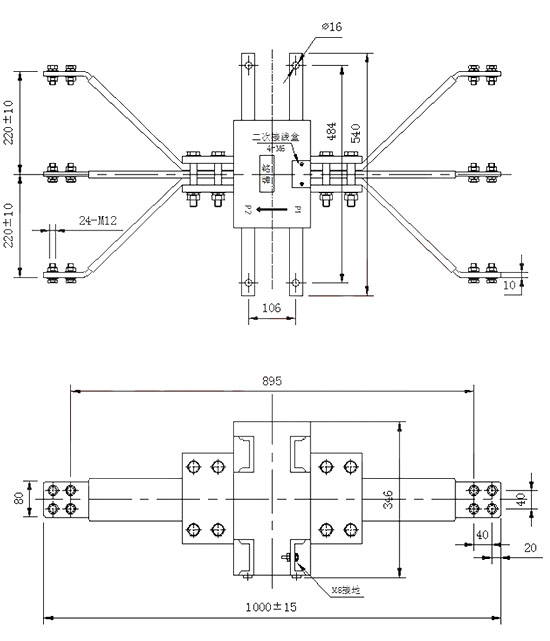
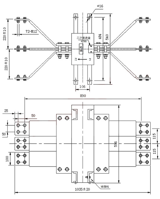
Outline Dimensions
| Model | Aperture Diameter (mm) |
Overall Height (mm) |
Mounting Hole Pattern (mm) |
|---|---|---|---|
| LJM-1 / LJM-2 / LJM-3 | phi80 | 180 | 120 x 120 |
| LJM-3L | phi100 | 210 | 140 x 140 |
Selection & FAQs
Selection Guide
- Select LJM-1 for 6kV, LJM-2 for 10kV, or LJM-3/LJM-3L for 15kV, then confirm the project insulation and withstand requirements.
- Check the complete conductor-group dimensions against the 80mm aperture of LJM-1/2/3 or the 100mm aperture of LJM-3L, including insulation clearance.
- Confirm the connected zero-sequence relay accepts a 5A CT secondary and that its pickup range matches the calculated earth-fault current.
- Obtain the model-specific thermal current, dynamic current, burden, insulation level and dimensional data before final protection coordination.
- Verify indoor environmental conditions, all-phase and screen/earth routing, K1/K2 polarity, mounting pattern and secondary shorting/grounding provision.
Frequently Asked Questions
Q1: What is the LJM bus-type zero-sequence CT used for?
It supplies a residual-current signal for detecting single-phase earth faults in indoor generators, motors, distribution feeders and switchgear at 6kV, 10kV or 15kV.
Q2: Which LJM model matches each voltage class?
LJM-1 is listed for 6kV, LJM-2 for 10kV, and LJM-3 or LJM-3L for 15kV. Final selection must also confirm project insulation and fault-withstand data.
Q3: What is the difference between LJM-3 and LJM-3L?
Both serve 15kV applications, but LJM-3L is the extended-capacity structure with a 100mm aperture; LJM-3 uses the standard 80mm aperture.
Q4: Does the LJM require a primary electrical connection?
No separate CT primary terminals are used. The protected phase cables or busbars pass through the central aperture and act as the primary conductors.
Q5: Which relay and secondary current are used?
The standard secondary is 5A and the published recommendation is DD11/60 or an equivalent zero-sequence relay with compatible input, burden and pickup characteristics.
Q6: Which conductors pass through the aperture?
All phase conductors of the protected circuit pass through together in the same direction. Neutral, screen, armour and earth routing must follow the protection scheme to preserve correct residual summation.
Q7: How should the secondary be handled during maintenance?
Never leave K1/K2 open while primary current can flow. Make the circuit safe, short the secondary through an approved terminal and apply the specified one-point grounding before disconnecting the relay.