Overview
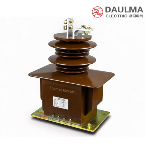
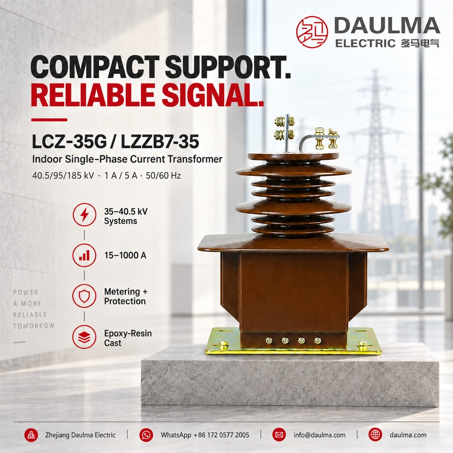
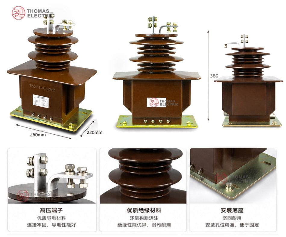
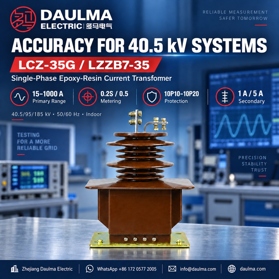
The LCZ-35G / LZZB7-35 is an indoor single-phase epoxy resin cast current transformer designed for 35kV / 36kV / 40.5kV AC power systems operating at 50Hz or 60Hz. It features a fully enclosed support-type structure with epoxy resin casting insulation, ensuring stable dielectric performance, moisture resistance, and mechanical robustness in indoor environments.
This transformer supports current measurement, energy metering, and relay protection functions, making it suitable for integration into 35kV-class indoor switchgear, air-insulated switchgear, and power metering cabinets. It complies with standard insulation coordination requirements for medium-voltage equipment rated up to 40.5kV system voltage.
Key Ratings Snapshot
| Parameter | Rating |
|---|---|
| System voltage class | 35kV / 36kV / 40.5kV |
| Rated insulation level | 40.5/95/185kV |
| Rated frequency | 50Hz or 60Hz |
| Phase | Single phase |
| Installation condition | Indoor |
| Insulation material | Epoxy resin cast |
| Structure type | Fully enclosed support-type |
| Rated secondary current | 5A or 1A |
| Application | Measurement, metering, protection |
| Typical installation | Indoor switchgear, metering cabinets |
Model Designation
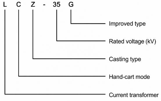
- L: Current transformer
- C: Epoxy resin cast insulation
- Z: Support-type (pillar-type) structure
- -35: Rated voltage class (35kV)
- G: Structural variant or series identifier
- /270f: Body-width platform code (270mm reference)
- /2: Number of secondary windings
Construction
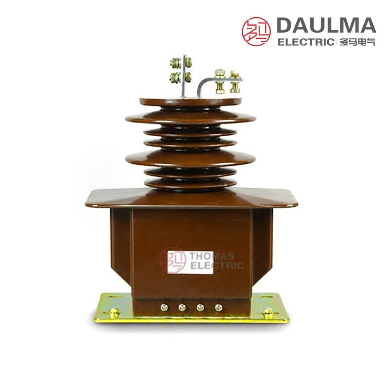
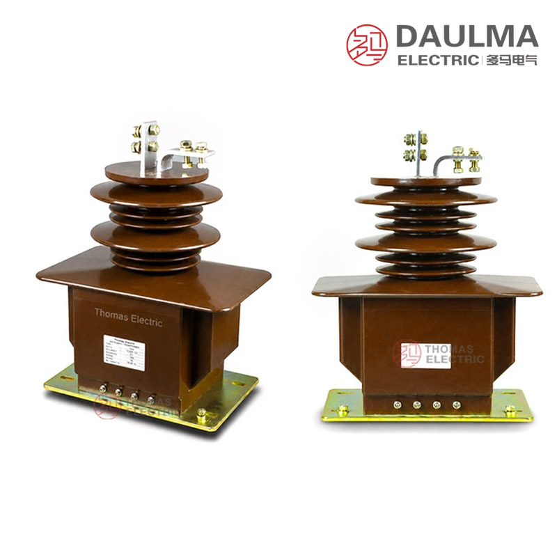
The LCZ-35G / LZZB7-35 current transformer employs a single-phase epoxy resin cast construction optimized for indoor use. The entire core and winding assembly is fully encapsulated within the epoxy resin body, providing excellent insulation integrity, resistance to humidity, and long-term operational reliability. The upper section houses the primary terminals (P1 and P2), while the lower section contains the secondary terminal block—typically labeled 1S1/1S2 and 2S1/2S2—and a mounting base for secure installation in switchgear panels. This compact, pillar-type design ensures adequate creepage distance and clearance for 40.5kV insulation coordination while maintaining a footprint suitable for space-constrained indoor distribution equipment.
Technical Parameters
Service Conditions
- Installation: Indoor installation for 35kV / 36kV / 40.5kV switchgear and distribution systems.
- Rated frequency: 50Hz or 60Hz.
- Ambient temperature: -5°C to +40°C.
- Humidity: Indoor environment without severe condensation; special humidity requirements should be confirmed by project agreement.
- Altitude: Standard indoor service; high-altitude applications require insulation coordination confirmation.
- Maintenance: Keep the resin surface clean and dry to maintain insulation performance.
Technical Parameters
The LCZ-35G (LZZB7-35) is an indoor single-phase epoxy resin cast current transformer designed for 35kV/36kV/40.5kV systems, with a rated insulation level of 40.5/95/185kV. It operates within an ambient temperature range of -5°C to +40°C, complies with IEC 61869 and GB/T 20840 standards, and supports primary current ratings from 15A to 1000A.
| Rated Primary Current (A) |
Accuracy Classes Combination |
Rated Output (VA) |
Rated Short-Time Thermal Current (kA/1S) |
Rated Dynamic Current (kA) |
|---|---|---|---|---|
| 15 | 0.2S/0.5 0.2(0.5)/10P10 0.2(0.5)/10P15 10P10/10P10 10P15/10P15 |
30/50 30/30 30/20 20/20 15/15 |
3 | 7.5 |
| 20 | 4 | 10 | ||
| 30 | 6 | 15 | ||
| 40 | 8 | 20 | ||
| 50 | 10 | 25 | ||
| 75 | 15 | 37.5 | ||
| 100 | 21 | 52.5 | ||
| 150 | 31.5 | 78.75 | ||
| 200 | 45 | 112.5 | ||
| 300 | ||||
| 400 | 0.2S/0.5 0.2(0.5)/10P10 0.2(0.5)/10P15 0.2(0.5)/10P20 10P10/10P10 10P15/10P15 |
50/50 50/30 50/20 50/15 30/30 20/25 |
63 | 157.5 |
| 500 | ||||
| 600 | ||||
| 800 | ||||
| 1000 | 80 | 200 |
Installation & Wiring
Installation Guidance
The LCZ-35G / LZZB7-35 is installed inside 35kV-class indoor switchgear or distribution cabinets. The base, primary terminal direction, secondary terminal position and insulation clearance must be checked against the approved outline drawing before installation. The catalogue drawing shows different terminal connection structures for 5A ≤ I1n ≤ 500A and 600A ≤ I1n ≤ 1000A, so the final drawing should be confirmed according to the selected primary current ratio.
| Installation Item | Recommended Check Point |
|---|---|
| Mounting base | Confirm base size, hole spacing, support strength and grounding position before installation. |
| Primary terminals | Check P1 / P2 direction, conductor connection method and phase-to-ground clearance. |
| Secondary terminal area | Reserve access space for wiring, testing, inspection and terminal marking. |
| Switchgear clearance | Confirm insulation clearance according to the 40.5kV equipment class. |
| Current range layout | Use the correct terminal structure for the selected current range. |
| Grounding | Ground one point of the secondary circuit and connect the equipment grounding point according to project design. |
| Drawing confirmation | Use the approved outline drawing and terminal diagram for final production and installation. |
Windings & Terminal Marking
The primary terminals are identified as P1 and P2. Secondary winding terminals are marked according to the number of secondary outputs, such as 1S1 / 1S2 for the measurement winding and 2S1 / 2S2 for the protection winding. The final marking shall follow the wiring diagram and product nameplate.
| Terminal | Function | Application Note |
|---|---|---|
| P1 / P2 | Primary terminals | Used for primary current direction and polarity reference. |
| 1S1 / 1S2 | First secondary winding | Usually assigned to metering or measurement circuit. |
| 2S1 / 2S2 | Second secondary winding | Usually assigned to relay protection circuit. |
| Additional S terminals | Extra secondary winding groups | Used for multi-core measurement or protection circuits according to project design. |
| Grounding point | Secondary circuit grounding reference | One point of the secondary circuit should be grounded according to project practice. |
Selection & FAQs
Selection Guide
- Confirm the exact LCZ-35G/270f/2 winding structure. The “/2” reference suggests two secondaries, but several accuracy lines show three functions; require a physical core and terminal schedule.
- Select the 15A–1000A ratio. Match operating current and fault duty, then choose the correct primary terminal structure for 15A–500A or 600A–1000A.
- Map every accuracy label to its VA. Published combinations include 0.2S/0.5, measurement with 10P10–10P20 and dual protection, but some three-label rows show only two burdens.
- Choose 1A or 5A with a full burden calculation. Include meter or relay inputs, cables, terminals and test equipment, and confirm outputs independently for each physical winding.
- Verify installation and dielectric data. Confirm base, primary direction, clearances, secondary access, partial discharge, altitude, 1-second thermal and peak dynamic current and IEC 61869 documents.
Frequently Asked Questions
Q1: Is this 35kV current transformer suitable for outdoor installation?
No, this model is strictly for indoor 35kV/40.5kV switchgear. The epoxy resin requires an environment free from severe condensation. Contact us for outdoor-rated alternatives if needed.
Q2: Which accuracy class combination is best for revenue metering?
Select the 0.2S class for high-precision revenue billing applications. It ensures accurate measurement across varying load conditions per IEC 61869 standards. Specify your exact metering requirements during order placement.
Q3: What is the rated short-time thermal current capacity?
The exact short-time thermal current depends on your selected primary rating from 15A to 1000A. Specific kA/1s values must be verified against your system fault levels. Provide your single-line diagram for factory confirmation.
Q4: Are these epoxy resin current transformers compliant with international standards?
Yes, the LCZ-35G fully complies with IEC 61869 and GB/T 20840 standards. It features a rated insulation level of 40.5/95/185kV for 35kV systems. Request the specific type test certificates during the procurement process.
Q5: Can this current transformer be manufactured for 60Hz power systems?
Yes, it supports both 50Hz and 60Hz rated frequencies. The core design and epoxy casting accommodate either frequency for 35kV indoor distribution. Confirm your grid frequency in the technical inquiry to ensure proper core sizing.
Q6: What applications are suitable for the LZZB7-35 single-phase current transformer?
This indoor epoxy resin cast model is ideal for 35kV, 36kV, and 40.5kV switchgear and distribution systems. It serves both measurement and protection functions. Consult our technical team for specific application engineering.
Q7: How should the epoxy resin surface be maintained for optimal insulation?
Keep the resin surface strictly clean and dry to maintain dielectric strength. Regular visual inspections for dust or moisture buildup are recommended in indoor environments. Contact our service department for detailed maintenance guidelines.