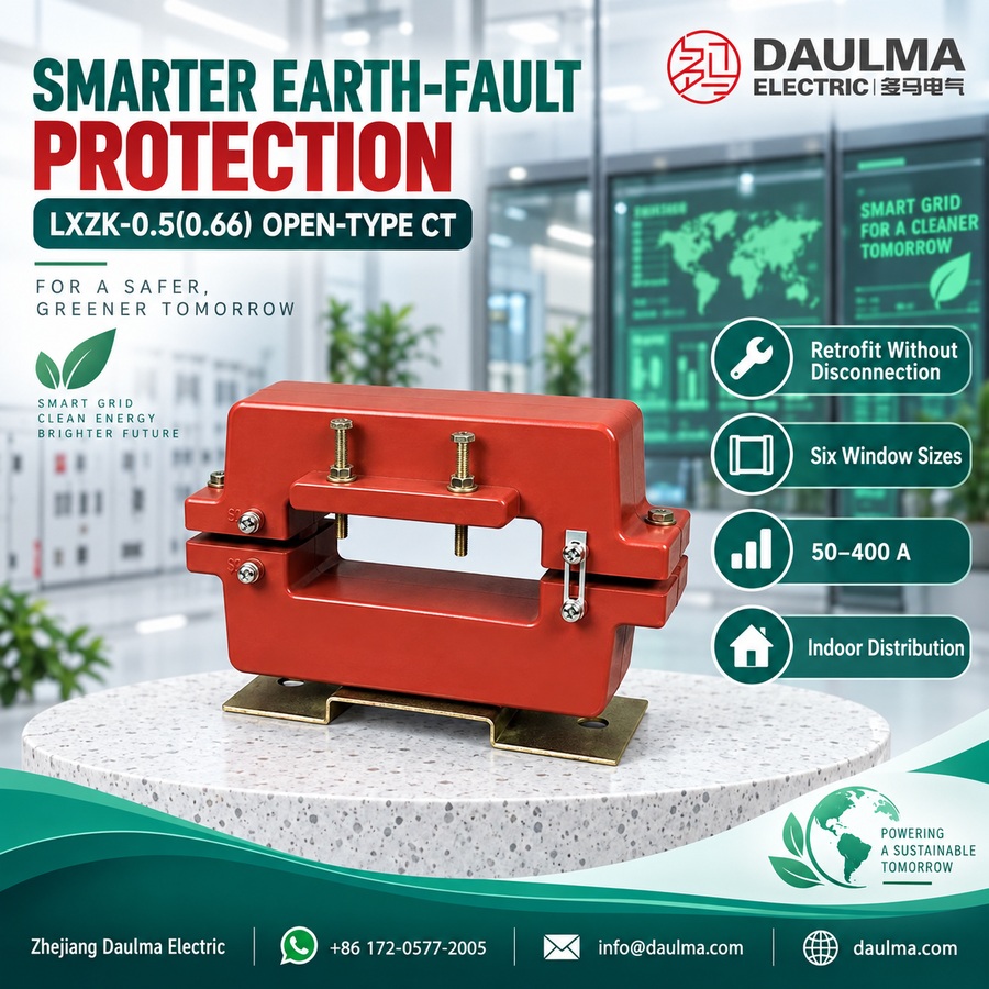
Overview
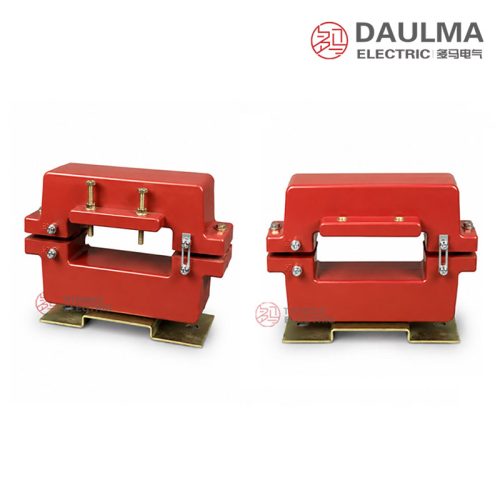
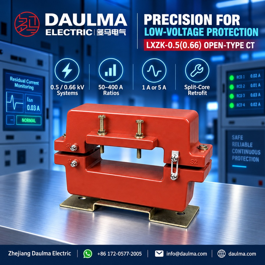
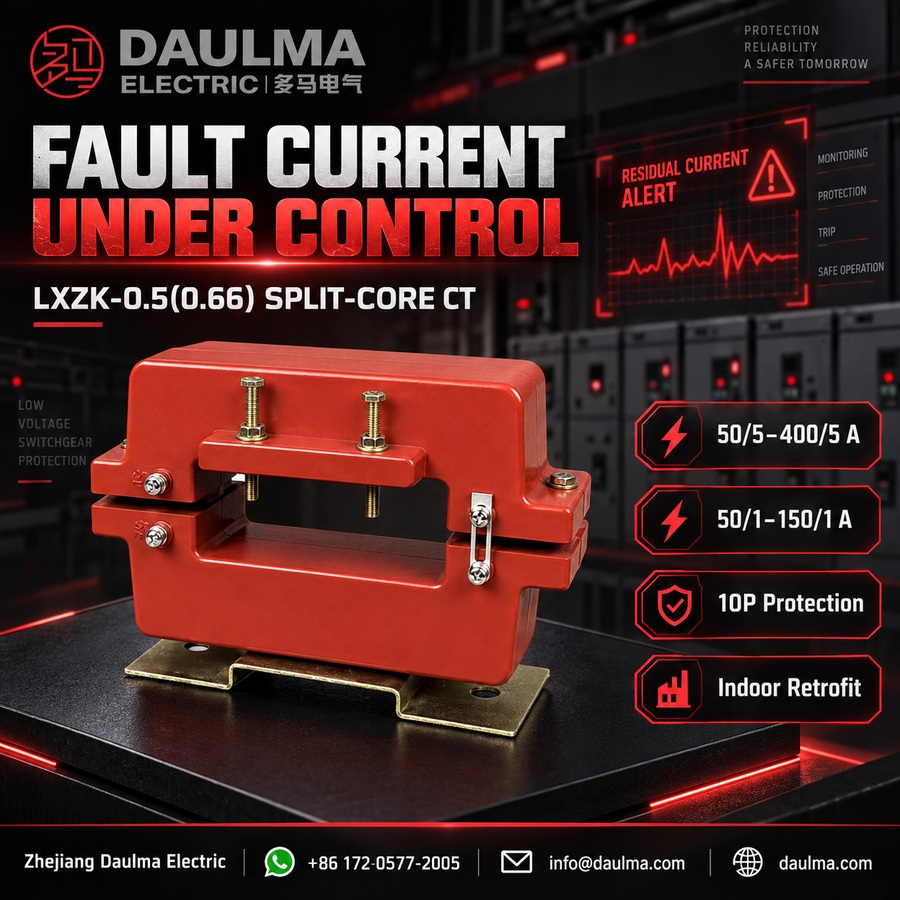
The LXZK-0.5(0.66) is an indoor open-type zero sequence current transformer with a cast-resin insulated structure, designed for low-voltage AC systems rated at 0.5 kV or 0.66 kV (corresponding to a rated insulation level of 0.72/3 kV). Its split-core design enables installation around existing conductors without disconnection.
Built for earth fault and residual current detection, it supports protection class ratings of 10P5, 10P10, or 10P15 depending on configuration. The transformer complies with standard requirements for indoor switchgear applications, including KHCT cabinets, motor/generator feeders, and distribution panels operating at 50 Hz or 60 Hz, delivering a secondary output of either 5A or 1A.
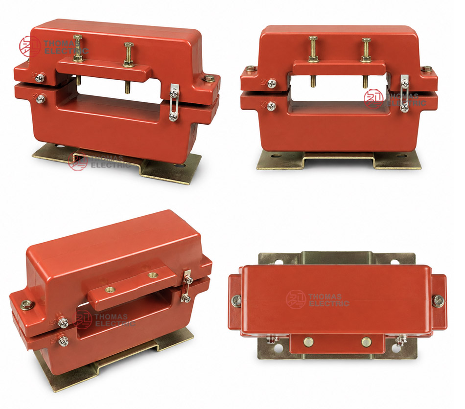
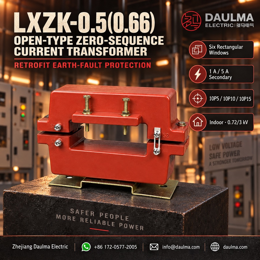
Key Ratings Snapshot
| Parameter | Rating |
|---|---|
| Voltage class | 0.5 kV / 0.66 kV |
| Rated insulation level | 0.72/3 kV |
| Rated frequency | 50 Hz / 60 Hz |
| Rated secondary current | 5 A or 1 A |
| Protection class | 10P5, 10P10, 10P15 |
| Installation environment | Indoor |
| Insulation material | Cast-resin |
| Core type | Split-core (openable) |
| Application | Zero sequence current detection for earth fault protection |
| Primary conductor | Cable or copper busbar (not disconnected during installation) |
| Secondary burden | As per selected protection class and ratio |
| Standards compliance | IEC 61869 series (typical for LV instrument transformers) |
Model Designation
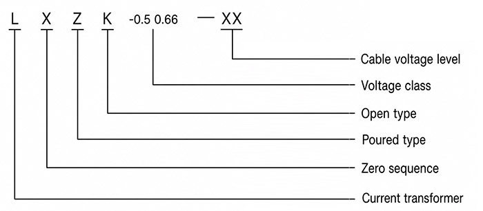
- L: Current transformer
- X: Zero sequence current transformer type
- Z: Cast-resin insulated structure
- K: Open-type / split-core structure
- 0.5 / 0.66: Voltage class code for indoor low-voltage systems
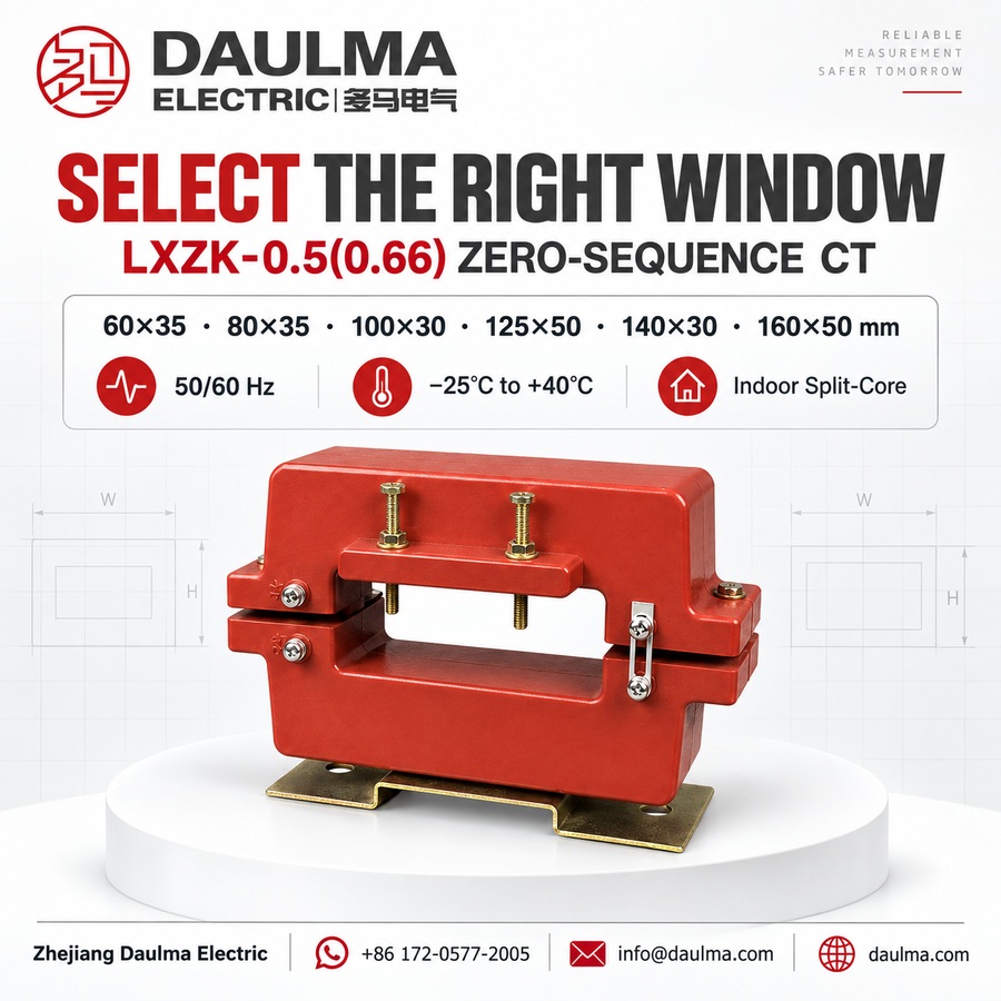
- 60×35, 80×35, etc.: Window size code for busbar or cable passage
Construction
The LXZK-0.5(0.66) features a robust cast-resin construction that fully encapsulates the magnetic core and secondary winding. This resin insulation provides high dielectric strength, excellent moisture resistance, and mechanical durability suitable for indoor switchgear environments. The split-core design consists of two hinged or separable halves that clamp securely around the primary conductor—either a power cable or copper busbar—without requiring disconnection. Once closed, the core forms a continuous magnetic path essential for accurate zero sequence current sensing. The secondary terminals are accessible via molded terminal blocks on the outer surface, ensuring safe and reliable connection to protection relays or monitoring devices. The rectangular window is precisely dimensioned to accommodate various busbar arrangements or multi-cable bundles as specified in the six available sizes.
Technical Parameters
Service Conditions
- Installation location: indoor
- Rated insulation level: 0.72/3kV
- Rated frequency: 50Hz / 60Hz
- Ambient temperature: -25°C to +40°C
- Installation environment: The installation environment should be free from severe vibration, corrosive gas, conductive dust, explosive medium, and heavy pollution.
- Split-core contact surface: The split-core contact surface should be clean and properly closed before operation.
- Conductor routing: The cable, copper busbar or conductor group should pass through the window without mechanical stress on the transformer body.
- Special requirements: For special conductor size, cabinet layout, protection relay, or burden requirements, technical confirmation is recommended before ordering.
Technical Parameters
The LXZK-0.5(0.66) is an open-type cast-resin zero sequence current transformer with a rated insulation level of 0.72/3kV, designed for indoor use within an ambient temperature range of -25°C to +40°C. It complies with GB 20840.1-2010 and GB 20840.2-2014 standards and supports secondary currents of 5A or 1A across primary current ratios from 50/5 to 400/5 (or 50/1 to 150/1).
| Specifications | Classes | Rated Current Ratio (A) / Rated Output (VA) | |||||||||||
|---|---|---|---|---|---|---|---|---|---|---|---|---|---|
| 50/5 | 75/5 | 100/5 | 150/5 | 200/5 | 250/5 | 300/5 | 400/5 | 50/1 | 75/1 | 100/1 | 150/1 | ||
| 60×35 | 10P5 | 1 | 2 | 2.5 | 3.75 | 5 | 7.5 | 7.5 | 10 | 1.5 | 2.5 | 2.5 | 3.75 |
| 10P10 | – | – | – | 1 | 2 | 2.5 | 2.5 | 3.75 | – | 1 | 1 | 2 | |
| 80×35 | 10P5 | 1 | 2 | 2.5 | 5 | 5 | 7.5 | 10 | 12.5 | 1.5 | 2.5 | 3.75 | 5 |
| 10P10 | – | – | 1 | 1.5 | 2.5 | 2.5 | 3.75 | 5 | – | 1 | 1.5 | 2 | |
| 100×30 | 10P5 | 1 | 2 | 2.5 | 3.75 | 5 | 7.5 | 10 | 10 | 1.5 | 2.5 | 3.75 | 5 |
| 10P10 | – | – | 1 | 1.5 | 2.5 | 2.5 | 3.75 | 5 | – | 1 | 1.5 | 2.5 | |
| 10P15 | – | – | – | – | – | 1 | 1.5 | 2.5 | – | – | – | – | |
| 125×50 | 10P5 | 1.5 | 2.5 | 3.75 | 5 | 7.5 | 7.5 | 10 | 15 | 1.5 | 2.5 | 3.75 | 5 |
| 10P10 | – | – | 1 | 1.5 | 2.5 | 2.5 | 3.75 | 5 | – | 1 | 1.5 | 2 | |
| 10P15 | – | – | – | – | 1 | 1 | 1.5 | 2.5 | – | – | – | – | |
| 140×30 | 10P5 | 1 | 2 | 2.5 | 5 | 5 | 7.5 | 10 | 15 | 1.5 | 2.5 | 3.75 | 5 |
| 10P10 | – | – | 1 | 1.5 | 2 | 2.5 | 3.75 | 5 | – | 1 | 1.5 | 22.5 | |
| 10P15 | – | – | – | – | 1 | 1 | 1.5 | 2.5 | – | – | – | – | |
| 160×50 | 10P5 | 1 | 2 | 2.5 | 5 | 5 | 7.5 | 10 | 15 | 1.5 | 2.5 | 3.75 | 5 |
| 10P10 | – | – | 1 | 1.5 | 2 | 2.5 | 3.75 | 5 | – | 1 | 1.5 | 2.5 | |
| 10P15 | – | – | – | – | 1 | 1 | 1.5 | 2.5 | – | – | – | – | |
Installation & Wiring
Installation Diagram
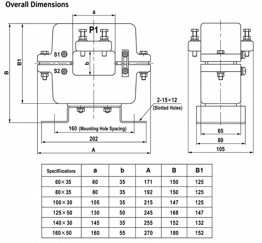
Window Size and Dimension Reference
| Specification | a (mm) |
b (mm) |
A (mm) |
B (mm) |
B1 (mm) |
Typical Selection Use |
|---|---|---|---|---|---|---|
| 60×35 | 60 | 35 | 171 | 150 | 125 | Small cable or narrow copper busbar layout |
| 80×35 | 80 | 35 | 192 | 150 | 125 | Medium cable or busbar cabinet layout |
| 100×30 | 105 | 35 | 215 | 147 | 125 | Flat copper busbar or compact feeder layout |
| 125×50 | 130 | 50 | 245 | 168 | 147 | Larger cable group or busbar layout |
| 140×30 | 145 | 35 | 255 | 152 | 132 | Long flat busbar or narrow-height cabinet layout |
| 160×50 | 160 | 55 | 270 | 180 | 152 | Large copper busbar or cable group application |
The LXZK series features an openable split-core design that allows installation around existing cables or copper busbars without disconnecting the primary conductors. To install, open the upper and lower core halves, position them around the complete group of phase conductors, then close and securely fasten the core using the provided locking bolts.
Selection & FAQs
Selection Guide
- Measure the complete phase-conductor or busbar group and choose the smallest window that provides safe clearance: 60×35, 80×35, 100×30, 125×50, 140×30 or 160×50mm.
- Confirm a 0.5kV or 0.66kV indoor system with a 0.72/3kV CT insulation rating and service conditions suitable for cast-resin equipment.
- Select a 1A or 5A secondary and a ratio within the applicable 50A–400A catalogue range to match the relay pickup and expected earth-fault current.
- Choose 10P5, 10P10 or an available 10P15 configuration, then verify that relay plus lead burden remains within the model-specific VA output.
- Review conductor, neutral, screen, armour and PE routing; allow access to clean, align and fully fasten both core halves without loading the resin body.
Frequently Asked Questions
Q1: What is the LXZK-0.5(0.66) designed to do?
It detects zero-sequence or residual current for earth-fault protection in indoor 0.5kV and 0.66kV distribution systems, switchgear and feeder circuits.
Q2: Can it be retrofitted without removing cables or busbars?
Yes. Its separable core opens around an existing conductor group, so primary conductors normally do not need to be disconnected during installation.
Q3: Which window size should be selected?
Choose the smallest of the six rectangular windows that safely clears the entire conductor group and fits the cabinet layout. Include insulation, bends, tolerances and installation access in the measurement.
Q4: What ratios and secondary currents are available?
Catalogue configurations use a 5A secondary from 50/5A to 400/5A or a 1A secondary from 50/1A to 150/1A. Availability and VA output depend on window size and protection class.
Q5: How is the correct protection class and burden chosen?
Match 10P5, 10P10 or the available 10P15 option to the relay study, then add the relay input and secondary wiring burdens. The total must not exceed the selected configuration’s rated VA.
Q6: Which conductors pass through the window?
The complete set of phase conductors must pass through together so balanced load currents cancel. Neutral, cable screen, armour and PE routing must follow the earth-fault protection scheme.
Q7: What installation mistakes can cause incorrect operation?
Contaminated or misaligned split faces, loose locking bolts, incorrect conductor or screen routing, excessive secondary burden and an open secondary circuit can reduce sensitivity or create a safety hazard.