Overview
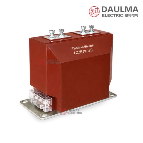
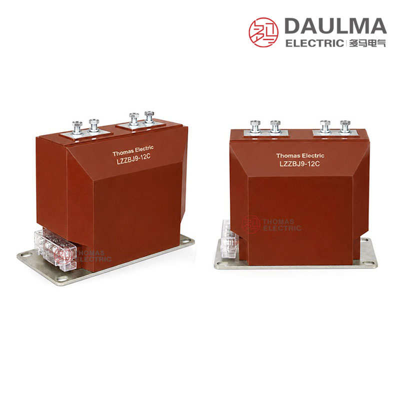
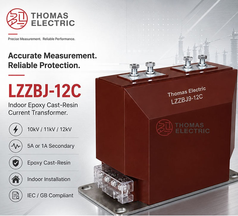
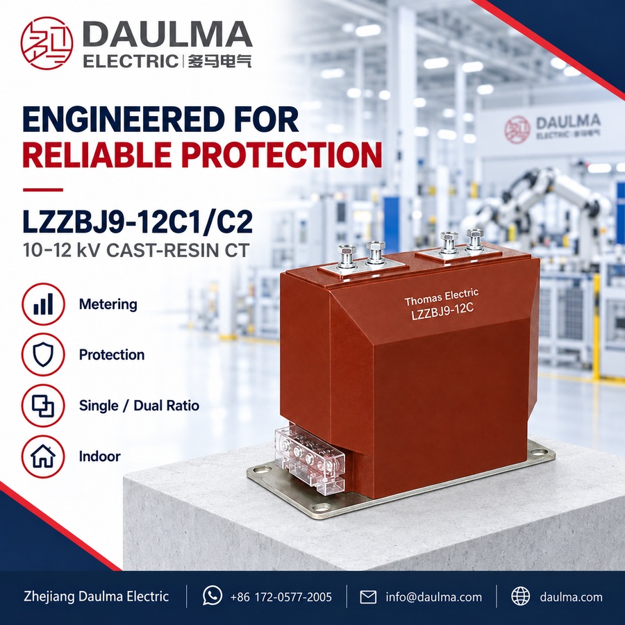
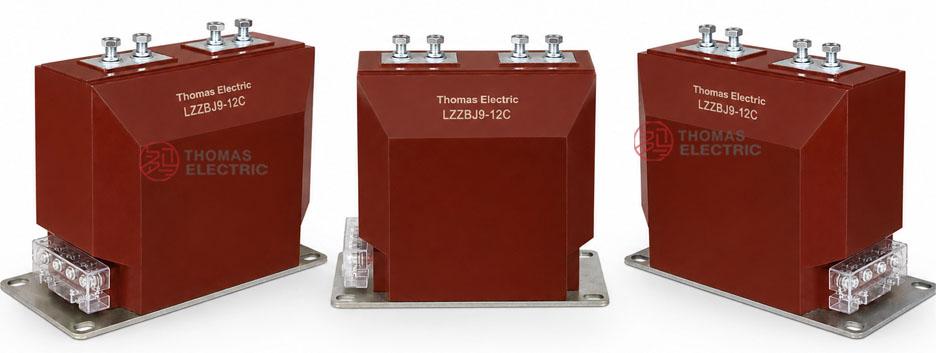
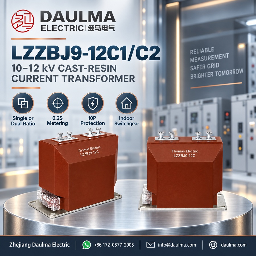
The LZZBJ9-12C1 and LZZBJ9-12C2 are indoor, single-phase, epoxy resin cast, fully enclosed post-type current transformers designed for 10kV–12kV medium-voltage power distribution systems. They feature a compact structure with primary and secondary windings and an annular magnetic core fully encapsulated in cast-resin insulation, ensuring high dielectric strength, moisture resistance, and mechanical stability for indoor switchgear applications.
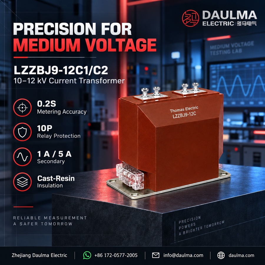
These transformers support both metering (accuracy classes 0.2S / 0.5) and protection (e.g., 10P) functions, making them suitable for feeder monitoring, energy metering, relay protection, and SCADA integration in 50Hz or 60Hz AC systems. They comply with IEC 60044-1 and can be aligned with IEC 61869-1/-2 standards per project requirements.
Key Ratings Snapshot
| Parameter | Rating |
|---|---|
| Voltage class | 10kV, 11kV, 12kV |
| Rated insulation level | 12/28/75kV or 12/42/75kV |
| Rated frequency | 50Hz / 60Hz |
| Rated secondary current | 1A or 5A |
| Metering accuracy | 0.2S, 0.5 |
| Protection accuracy | 10P (as configured) |
| Ratio configuration | Single or double ratio |
| Installation type | Indoor post-type in switchgear |
| Insulation material | Epoxy resin cast |
| Phase | Single-phase |
| Core type | Annular magnetic core |
| Applicable standards | IEC 60044-1; IEC 61869-1/-2 (optional) |
Model Designation
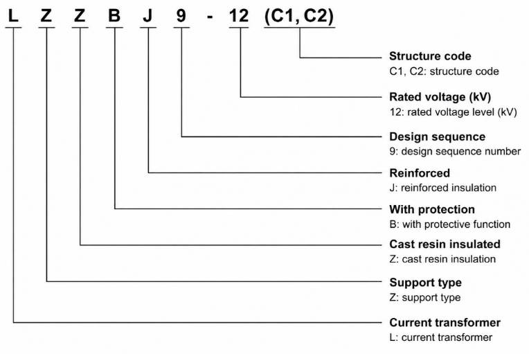
- L: Current transformer
- Z: Indoor type
- Z: Cast-resin insulated / fully enclosed structure
- B: Protection configuration available for metering and relay protection applications
- J: Reinforced design / enhanced insulation structure
- 9: Design sequence / product platform
- 10 / 12: Rated voltage class identification; used for 10kV, 11kV, or 12kV project applications according to insulation level and switchgear specification
- C1 / C2: Mechanical structure and ratio configuration variants for switchgear installation
Construction
The LZZBJ9-12C1 and LZZBJ9-12C2 current transformers employ a fully enclosed post-type construction, with the primary winding, secondary winding, and annular magnetic core integrally cast within a solid epoxy resin body. This cast-resin insulation provides excellent electrical isolation between the high-voltage primary circuit and low-voltage secondary circuit, while also delivering robust mechanical support, moisture resistance, and thermal stability. The post-type design enables direct mounting in medium-voltage switchgear as both a current-sensing device and a structural support component. The C1 and C2 variants differ in terminal orientation, core arrangement, and internal ratio configuration to accommodate diverse switchgear layouts and application-specific requirements for metering and protection circuits.
Technical Parameters
Service Conditions
- Installation location: Indoor medium-voltage switchgear
- System voltage: 10kV, 11kV, or 12kV class
- Rated frequency: 50Hz / 60Hz
- Ambient temperature: -5°C to +40°C
- Altitude: ≤1000m under standard service conditions
- Installation environment: Free from severe vibration, conductive dust, corrosive gas, explosive media, heavy contamination, and abnormal condensation.
- Special conditions: For high-altitude, high-humidity, coastal, heavy-dust, or special switchgear applications, technical confirmation is required before ordering.
Technical Parameters
The LZZBJ9-12C1/C2 is a cast-resin insulated current transformer designed for 10kV–12kV indoor switchgear applications. It operates within an ambient temperature range of -5°C to +40°C and at altitudes up to 1000m, complying with IEC 60044-1 and IEC 61869 standards. The transformer supports primary current ratios from 10A to 3150A and secondary currents of 1A or 5A, with multiple accuracy class combinations for metering and protection applications.
LZZBJ9-10C1 / 12C1 Single Ratio Selection Reference
| Rated Ratio (A) |
Accuracy Class Combination |
Rated Output (VA) | ALF | FS | Short-Time Thermal Current Ith (1s) |
Rated Dynamic Current Idyn |
||
|---|---|---|---|---|---|---|---|---|
| 0.2S | 0.5 | 10P | ||||||
| 10–200/5 | 0.2S / 0.2S 0.2S / 0.5 0.2S / 10P 0.5 / 10P 0.2S / 0.5 / 10P 0.2 / 0.5 / 10P |
10 or 15 | 15 | 15 | 10 / 15 / 20 | 5 or 10 | 150 × I1n | 375 × I1n |
| 300/5 | 31.5kA | 80kA | ||||||
| 400/5 | 31.5kA | 80kA | ||||||
| 500/5 | 40kA | 100kA | ||||||
| 600/5 | 50kA | 125kA | ||||||
| 800/5 | 63kA | 125kA | ||||||
| 1000/5 | 20 | 80kA | 160kA | |||||
| 1200–1500/5 | 80kA | 160kA | ||||||
| 1500–2000/5 | 100kA | 160kA | ||||||
| 2000–2500/5 | 130kA | 160kA | ||||||
LZZBJ9-10C1 / 12C1 Double Ratio Selection Reference
| Rated Ratio (A) |
Accuracy
Class |
Rated Output (VA) | ALF | FS | Short-Time
Thermal Current Ith (1s) |
Rated
Dynamic Current Idyn |
||
|---|---|---|---|---|---|---|---|---|
| 0.2S | 0.5 | 10P | ||||||
| 10–20/5 | 0.2S / 0.2S 0.2S / 0.5 0.2S / 10P 0.5 / 10P |
10 or 15 | 15 | 15 | 10 / 15 / 20 | 5 or 10 | 1.5kA | 3.75kA |
| 20–40/5 | 3kA | 7.5kA | ||||||
| 50–100/5 | 8kA | 20kA | ||||||
| 100–200/5 | 15kA | 37.5kA | ||||||
| 200–400/5 | 30kA | 75kA | ||||||
| 400–800/5 | 20 | 63kA | 130kA | |||||
| 500–1000/5 | 80kA | 160kA | ||||||
LZZBJ9-10C2 / 12C2 Single Ratio Selection Reference
| Rated Ratio (A) |
Accuracy
Class |
Rated Output (VA) | ALF | FS | Short-Time
Thermal Current Ith (1s) |
Rated
Dynamic Current Idyn |
||
|---|---|---|---|---|---|---|---|---|
| 0.2S | 0.5 | 10P | ||||||
| 10–200/5 | 0.2S / 0.2S 0.2S / 0.5 0.2S / 10P 0.5 / 10P 0.2S / 0.5 / 10P 0.2 / 0.5 / 10P |
10 or 15 | 15 | 15 or 20 | 10 / 15 / 20 | 5 or 10 | 150 × I1n | 375 × I1n |
| 300/5 | 31.5kA | 80kA | ||||||
| 400/5 | 31.5kA | 80kA | ||||||
| 500/5 | 40kA | 100kA | ||||||
| 600/5 | 50kA | 125kA | ||||||
| 800/5 | 63kA | 125kA | ||||||
| 1000/5 | 80kA | 160kA | ||||||
| 1200–1500/5 | 80kA | 160kA | ||||||
| 1500–2000/5 | 80kA | 160kA | ||||||
| 2000–2500/5 | 100kA | 160kA | ||||||
| 2500–3150/5 | 130kA | 160kA | ||||||
Installation & Wiring
Installation Diagram
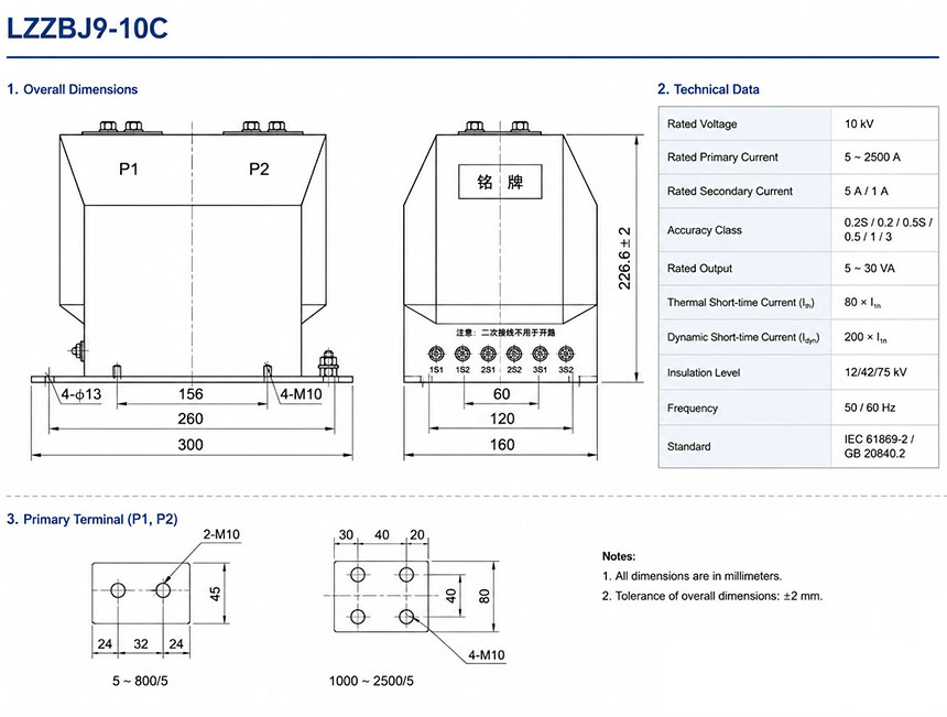
The LZZBJ9-12C1/C2 epoxy resin cast current transformer is designed for indoor post-type support installation within medium-voltage switchgear. Mounting must align with approved outline drawings to ensure proper phase-to-ground clearance, busbar connection geometry, and maintenance access.
Windings and Terminal Marking
| Terminal Marking | Function | Application Note |
|---|---|---|
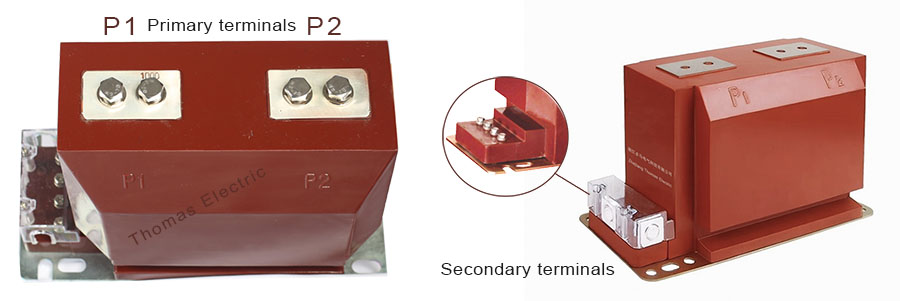
| P1 / P2 | Primary terminals | The reference primary current direction is normally defined from P1 to P2. |
| 1S1 / 1S2 | First secondary winding | Usually used for metering, measurement, or the first specified secondary core. |
| 2S1 / 2S2 | Second secondary winding | Usually used for relay protection or an additional secondary circuit when required. |
| 3S1 / 3S2 | Optional third secondary winding | Used when a three-core metering/protection configuration is required by the project. |
Selection & FAQs
Selection Guide
- Choose C1 or C2 from the approved mechanical and winding drawing. The variants differ in terminal orientation, core arrangement and ratio configuration, but the source does not provide a complete side-by-side dimensional comparison.
- Use the complete C1 schedule for preliminary ratio selection. Single-ratio C1 data extends from 10/5A to 2500/5A and dual-ratio data to 500–1000/5A; C2 and 3150A require separate documented confirmation.
- Decide between single and dual ratio before specifying cores. A dual ratio can support future load stages, but accuracy, output and protection performance must be guaranteed at both taps.
- Define two- or three-core performance. Available combinations include 0.2S/0.2S, 0.2S/0.5, 0.2S/10P, 0.5/10P and selected three-core metering/protection arrangements with per-core burdens.
- Confirm insulation and fault duty for the exact variant. Resolve whether 12/28/75kV or 12/42/75kV applies, then verify FS, ALF, short-time duration, peak dynamic current, busbar geometry, mounting and terminal access.
Frequently Asked Questions
Q1: Can this 12kV current transformer operate in high-altitude environments?
Yes, but standard models are limited to altitudes ≤1000m. For higher elevations, technical confirmation and design adjustments are required. Contact our team for high-altitude project verification.
Q2: Which accuracy class combination is best for protection relays?
Select 5P or 10P accuracy classes for protection applications. These ensure reliable performance during fault conditions per IEC 61869 standards. Specify your exact protection class during ordering.
Q3: Why is technical confirmation required for coastal switchgear applications?
Coastal environments introduce heavy contamination and corrosive gases. Standard models require a clean environment free from abnormal condensation. Request special insulation treatments for coastal projects during inquiry.
Q4: Can we customize the primary current ratio for specific loads?
Yes, primary current ratios are customizable from 10A up to 3150A. Secondary currents can be configured for 1A or 5A outputs. Provide your exact ratio requirements for factory quotation.
Q5: Are these current transformers compliant with international IEC standards?
Yes, the LZZBJ9-12C1/C2 fully complies with IEC 60044-1 and IEC 61869 standards. Compliance certificates and type test reports are available. Request documentation from our sales team during procurement.
Q6: Is this epoxy resin cast CT suitable for medium-voltage switchgear?
Yes, it is specifically designed for 10kV to 12kV indoor medium-voltage switchgear. The epoxy resin casting ensures reliable insulation and compact dimensions. Confirm your switchgear dimensions with our technical team.