Zero-Sequence Current Transformer Protection Principle and Applications
- Introduction
- Working Principle of Zero-Sequence Current Transformers
- Protection Applications of Zero-Sequence Current Transformers
- Installation Methods of Zero-Sequence Current Transformers
- Zero-Sequence Current Transformer Installation Process
- Differences Between Zero-Sequence CTs and Conventional CT
- Conclusion
Introduction
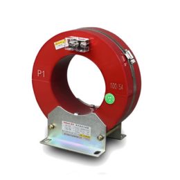
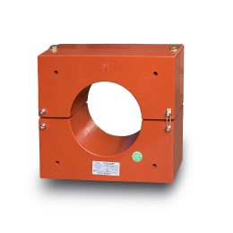
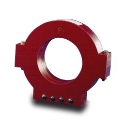
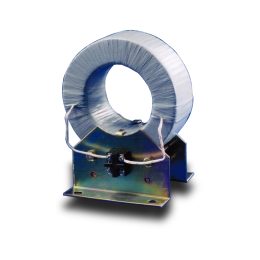
Zero-sequence current transformers (ZCTs) play a crucial role in electrical power systems by detecting ground faults and ensuring the safe and stable operation of power networks. They work in conjunction with protective relays and monitoring systems to detect zero-sequence currents caused by ground faults or unbalanced loads. By providing accurate fault detection, ZCTs help prevent damage to electrical equipment and enhance the reliability of power distribution.
This article explores the working principles of zero-sequence current transformers, their role in power system protection, installation methods, and the differences between ZCTs and conventional current transformers.
Working Principle of Zero-Sequence Current Transformers
The operation of a zero-sequence current transformer is based on Kirchhoff’s Current Law, which states that the algebraic sum of all currents entering a node is equal to zero.
- Under normal conditions, when the three-phase system is balanced (i.e., no ground faults or significant leakage currents), the vector sum of the three-phase currents is zero:
Ia + Ib + Ic = 0
As a result, no magnetic flux is generated in the ZCT’s core, and the secondary winding does not produce an output signal. - When an unbalanced load exists in the system, a small zero-sequence current appears due to the imbalance. This current, denoted as IN, represents the deviation from perfect balance in the three-phase system.
- In the case of a ground fault, a fault current Id flows from the faulted phase to the ground. This results in a measurable zero-sequence current, given by:
Io = IN + Id
Here, Io represents the sum of the unbalanced current and the ground fault current. This induced current in the ZCT’s secondary winding is then processed by protective relays to trigger alarms or disconnect faulty circuits.
Protection Applications of Zero-Sequence Current Transformers
Zero-sequence current transformers are widely used in power systems for detecting ground faults and ensuring electrical safety. Their primary applications include:
1. Ground Fault Protection in Neutral-Grounded Systems
- In TN grounding systems, a ground fault results in a significant zero-sequence current. The ZCT detects this current and sends a signal to protection relays, which isolate the faulty circuit to prevent further damage.
- TN-S and TN-C-S systems have low-impedance grounding paths, making zero-sequence protection highly effective.
- In TT grounding systems, ground fault currents are weaker due to the high grounding resistance, making it challenging for ZCTs to detect faults accurately.
2. Ground Fault Detection in Isolated and High-Impedance Grounded Systems
- IT grounding systems are commonly used in industrial applications where continuity of power supply is critical. In these systems, the first ground fault does not cause immediate disconnection but generates a leakage current that needs to be detected.
- ZCTs monitor this leakage current and activate alarms, allowing operators to address insulation faults before a second fault occurs.
3. Residual Current Protection for Electrical Safety
- ZCTs are used in leakage current protection (residual current devices, RCDs) to detect unintended current paths to the ground, protecting humans from electric shocks.
- When a leakage current exceeds a predefined threshold, the ZCT triggers a circuit breaker to disconnect the supply.
4. Protection of Distribution Networks and Industrial Equipment
- ZCTs are installed in medium-voltage and low-voltage switchgear to detect ground faults and trip protective relays when necessary.
- In industrial applications, electric motors, generators, and transformers are protected by ZCTs to prevent insulation breakdown due to ground faults.
Installation Methods of Zero-Sequence Current Transformers
Proper installation of ZCTs is critical for accurate detection and reliable system operation. There are different methods for installing ZCTs, depending on the system configuration.
1. Three-Phase System with Individual Current Transformers
- Each phase is equipped with a separate current transformer (CT).
- The ZCT calculates the sum of the individual phase currents to determine the zero-sequence current.
2. Single Zero-Sequence Current Transformer for All Three-Phase Conductors
- Instead of using individual CTs, all three-phase conductors are passed through a single zero-sequence CT.
- This method simplifies installation and ensures accurate detection of zero-sequence currents.
3. Zero-Sequence Current Transformer Installed on the Neutral Conductor
- In some systems, the ZCT is installed around the neutral conductor (N).
- This configuration is useful in systems where ground faults occur at the transformer neutral point.
Zero-Sequence Current Transformer Installation Process
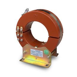
For accurate and reliable operation, ZCTs must be installed correctly. The installation process depends on whether an integral (closed-core) ZCT or a split-core (open-core) ZCT is used.
1. Integral (Closed-Core) ZCT Installation
- The transformer must be installed before cable laying.
- The power cable should pass through the ZCT during installation.
2. Split-Core (Open-Core) ZCT Installation
- The transformer can be installed after the power cable has been laid.
- The process involves:
- Removing the connection plates from terminals “K1′” and “K2′” (not required for circular ZCTs).
- Loosening and removing the screws securing the core.
- Placing the transformer around the cable and securing it properly.
- Cleaning the contact surfaces and applying a thin layer of anti-corrosion oil.
- Aligning and securing the transformer’s two halves.
- Fixing the connection plates back onto “K1′” and “K2′” if required.
For ZCTs with an inner diameter larger than 120mm installed horizontally, a non-magnetic support should be used to maintain stability.
Differences Between Zero-Sequence CTs and Conventional CT
Zero-sequence current transformers differ from conventional current transformers (CTs) in several ways:
| Feature | Zero-Sequence Current Transformer (ZCT) | Conventional Current Transformer (CT) |
|---|---|---|
| Purpose | Detects zero-sequence currents (ground faults) | Measures phase currents for metering or protection |
| Output Signal | Proportional to the sum of three-phase currents (Io) | Proportional to the current in a single conductor |
| Application | Ground fault protection, leakage detection | Overcurrent protection, phase current measurement |
| Installation | Encircles all phase conductors or neutral conductor | Installed on individual phase conductors |
Conclusion
Zero-sequence current transformers are essential components in modern power systems, enabling accurate detection of ground faults and ensuring electrical safety. By monitoring the zero-sequence current, ZCTs provide critical protection against leakage currents, insulation breakdowns, and electrical faults. Their applications in ground fault protection, system monitoring, and residual current detection make them indispensable for both industrial and commercial power systems.
To maximize the effectiveness of ZCTs, proper selection, installation, and maintenance are essential. Following industry standards for installation, regularly inspecting the equipment, and using high-quality ZCTs will ensure reliable operation and enhanced system protection. With advancements in power protection technology, zero-sequence current transformers will continue to play a vital role in electrical safety and system reliability.
- Analysis of the Impact of Incorrect CT S1 and S2 Connections and Reversed Input Lines
- 4 Common Causes of 10kV Three-Phase Five-Pole Voltage Transformer Failures and Solutions
- Magnetic Saturation in 20kV Voltage Transformers and Its Adverse Effects
- Common Fault Handling for Current and Voltage Transformers
- Common Faults and Troubleshooting of Current Transformers Faults
- Working Principle of Zero-Sequence Current Transformers
