Overview
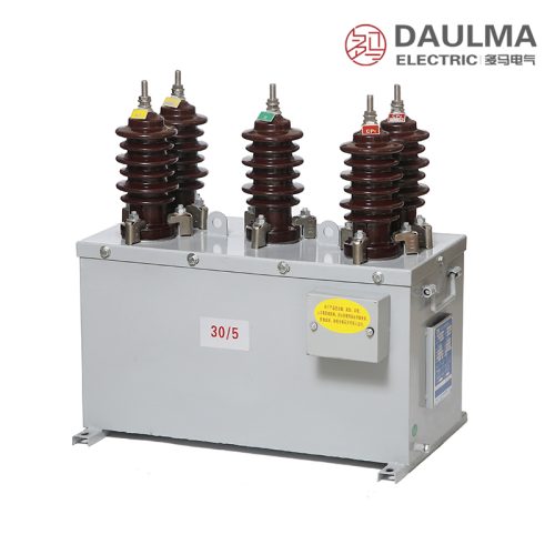
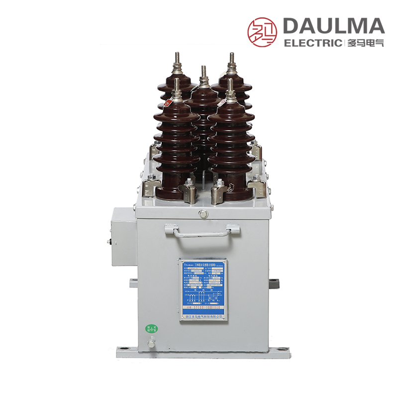
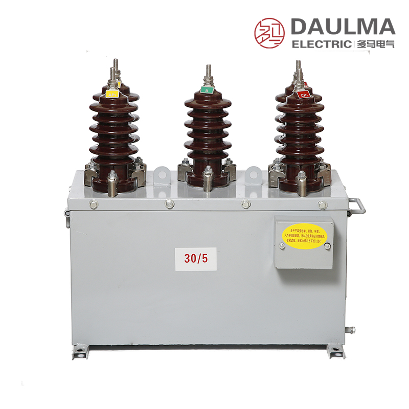
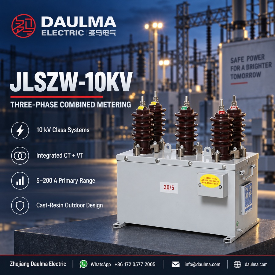
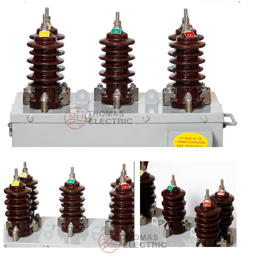
The JLSZW-10 is a three-phase combined instrument transformer integrating voltage (VT) and current (CT) transformation functions in a single outdoor-rated assembly. Designed for 10 kV class medium-voltage systems, it features cast-resin insulation for both VT and CT sections, ensuring robust performance in harsh outdoor environments.
Offering metering accuracy up to 0.2S (CT) and 0.2 (VT), the unit supports revenue-grade energy metering, relay protection, and power quality monitoring in distribution networks. It complies with GB/T 20840 series standards and is suitable for pole-mounted installations, urban/rural grids, industrial substations, and smart grid applications.
Key Ratings Snapshot
| Parameter | Rating |
|---|---|
| System voltage class | 10 kV |
| Rated frequency | 50 Hz (60 Hz optional) |
| Configuration | Three-phase V/V (2 VT + 2 CT) |
| VT ratio | 3000/100 V, 6000/100 V, or 10000/100 V |
| CT ratio | 5–200/5 A |
| VT accuracy | 0.2 / 0.5 class |
| CT accuracy | 0.2S / 0.2 class |
| VT rated output | 15 / 30 VA per core |
| CT rated output | 10 VA per core |
| Burden power factor | cosφ = 0.8 (lagging) |
| Short-circuit withstand (CT) | Ith: 100×I₁n (1 s), Idyn: 2.5×Ith (peak) |
| Insulation level | Up to 12/42/75 kV (Um/ACWV/BIL) |
Model Designation
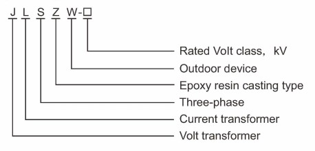
- J: Combined instrument transformer (VT + CT integrated assembly)
- L: Current transformer section designation
- S: Three-phase configuration (three-wire system)
- Z: Cast-resin (epoxy) insulated structure
- W: Outdoor service rating
- 10: Voltage class (kV)
Construction
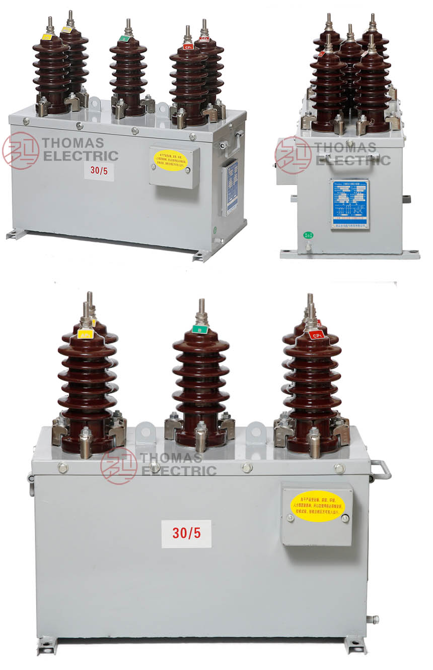
The JLSZW-10 features an integrated three-phase design housed in a fully sealed, weatherproof metal enclosure suitable for outdoor service. Both voltage and current transformer sections utilize epoxy resin cast insulation: the VT employs an open magnetic core, while the CT uses a toroidal closed core made of high-quality cold-rolled silicon steel. This construction delivers excellent moisture resistance, UV stability, and long-term dielectric reliability. The V/V connection scheme—comprising two VTs and two CTs—optimizes space for three-phase three-wire metering. Outdoor-rated terminals with weather sealing ensure secure connections, and the metal cabinet provides electromagnetic shielding and mechanical protection. Terminal markings follow standard polarity conventions (A-X/a-x for VT; P1-P2/1S1-1S2 for CT) to guarantee correct phase alignment and measurement accuracy.
Technical Parameters
Service Conditions
- Installation environment: Outdoor installation with protection from direct weather exposure
- Altitude: ≤ 1000 m (higher altitude shall be specified for engineering confirmation)
- Ambient temperature: −25 °C to +40 °C
- Relative humidity: Daily average ≤ 95%, monthly average ≤ 90%
- Environmental conditions: Suitable for outdoor use; resistant to moisture, dust, and pollution; withstands normal mechanical shock and vibration in distribution environments
- Pollution severity: Suitable for moderate pollution environments (site-specific assessment required for heavy industrial areas)
Technical Parameters
The JLSZW-10 is a three-phase combined outdoor instrument transformer for 10 kV class AC systems (50 Hz), featuring cast-resin insulation and designed for operation within an ambient temperature range of −25 °C to +40 °C at altitudes up to 1000 m. It complies with applicable standards for measurement accuracy and short-circuit withstand capability, supporting primary current ratios from 5–200 A.
Voltage Transformer Data
| Model | Rated Voltage Ratio (V) |
Accuracy Class |
Rated Output (VA) |
Maximum Output (VA) |
Rated Insulation Level (kV) |
|---|---|---|---|---|---|
| JLSZW-6/10 | 3000/100 | 0.2 / 0.5 | 15 / 30 | 300 | 3.6/25/40 |
| JLSZW-6/10 | 6000/100 | 0.2 / 0.5 | 15 / 30 | 300 | 7.2/32/60 |
| JLSZW-6/10 | 10000/100 | 0.2 / 0.5 | 15 / 30 | 300 | 12/42/75 |
Current Transformer Data
| Model | Rated Current Ratio (A) |
Accuracy Class |
Rated Output (VA) |
Short-Time Thermal Current |
Dynamic Current |
Rated Insulation Level (kV) |
|---|---|---|---|---|---|---|
| JLSZW-6/10 | 5~200/5 | 0.2S | 10 | 100 I₁n | 2.5 I₁th | 12/42/75 |
| JLSZW-6/10 | 5~200/5 | 0.2 | 10 | 100 I₁n | 2.5 I₁th | 12/42/75 |
Installation & Wiring
Outline Dimensions
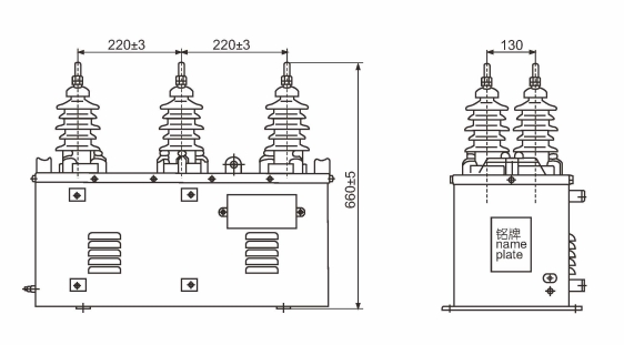
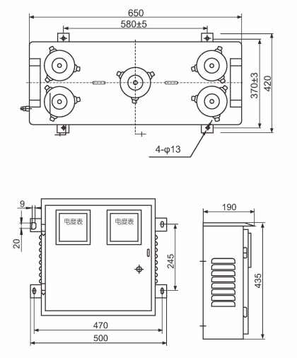
The outline dimensions shown above provide critical mounting and clearance information for the JLSZW-10 three-phase combined transformer. These drawings detail overall physical size, mounting hole positions, primary terminal locations, and secondary wiring access points to ensure proper installation on poles or walls in outdoor environments.
Selection & FAQs
Selection Guide
- Specify voltage and current transformer ratios (e.g., 10000/100 V and 100/5 A) according to system requirements.
- Define accuracy classes for both VT (e.g., 0.2 / 0.5) and CT (e.g., 0.2S) based on metering or protection needs.
- Indicate rated burden (in VA) for each secondary core of both VT and CT to ensure compatibility with connected devices.
- Select the appropriate connection scheme—standard V/V is typical for three-phase three-wire systems without neutral.
- Confirm environmental conditions such as temperature range, altitude, and pollution level if they deviate from standard ratings.
- State any special requirements including IP rating, terminal arrangement, documentation language, or certification needs at ordering stage.
Frequently Asked Questions
Q1: Can this 10kV combined transformer be installed at high altitudes?
Standard models are rated for altitudes up to 1000 meters. For installations exceeding this limit, derating or custom design is required. Please specify your exact site altitude for engineering confirmation.
Q2: Which accuracy classes are available for the voltage section?
Standard accuracy classes include 0.2, 0.5, and 3P for measurement and protection. The exact class depends on your rated output and burden requirements. Contact us with your specific VA load for precise selection.
Q3: Is this outdoor transformer suitable for heavy pollution environments?
It is designed for moderate pollution environments with cast-resin insulation. For heavy industrial or severe pollution sites, site-specific creepage distance assessments are necessary. Please provide the pollution severity level for factory evaluation.
Q4: Can the primary current ratio be customized for my project?
Yes, primary current ratios can be customized within the 5A to 200A range. Standard ratios are available from stock, while non-standard ratios require factory confirmation. Specify your exact ratio requirements during inquiry.
Q5: What routine factory tests are performed before shipment?
Each unit undergoes standard routine tests including ratio, polarity, insulation resistance, and withstand voltage checks. Specific type tests or third-party certifications are subject to project requirements. Request the detailed test report outline for your order.
Q6: What are the main applications for this 10kV instrument transformer?
It is primarily used for energy metering, current measurement, and voltage monitoring in 10kV outdoor AC power systems. The cast-resin design ensures reliable operation in distribution networks. Contact us for application-specific technical datasheets.
Q7: How does this combined unit handle grid short-circuit currents?
The transformer complies with applicable standards for rated short-time thermal and dynamic current withstand capabilities. Exact short-circuit ratings depend on the selected primary current ratio. Provide your system short-circuit level for precise verification.
Q8: Are cast-resin outdoor instrument transformers available for 50Hz systems?
Yes, the JLSZW-10KV is specifically designed for 50Hz AC power systems. The cast-resin insulation provides excellent weather resistance for outdoor distribution applications. Confirm your system frequency and environmental conditions during the initial inquiry.