Overview
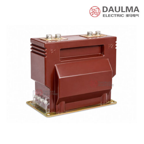
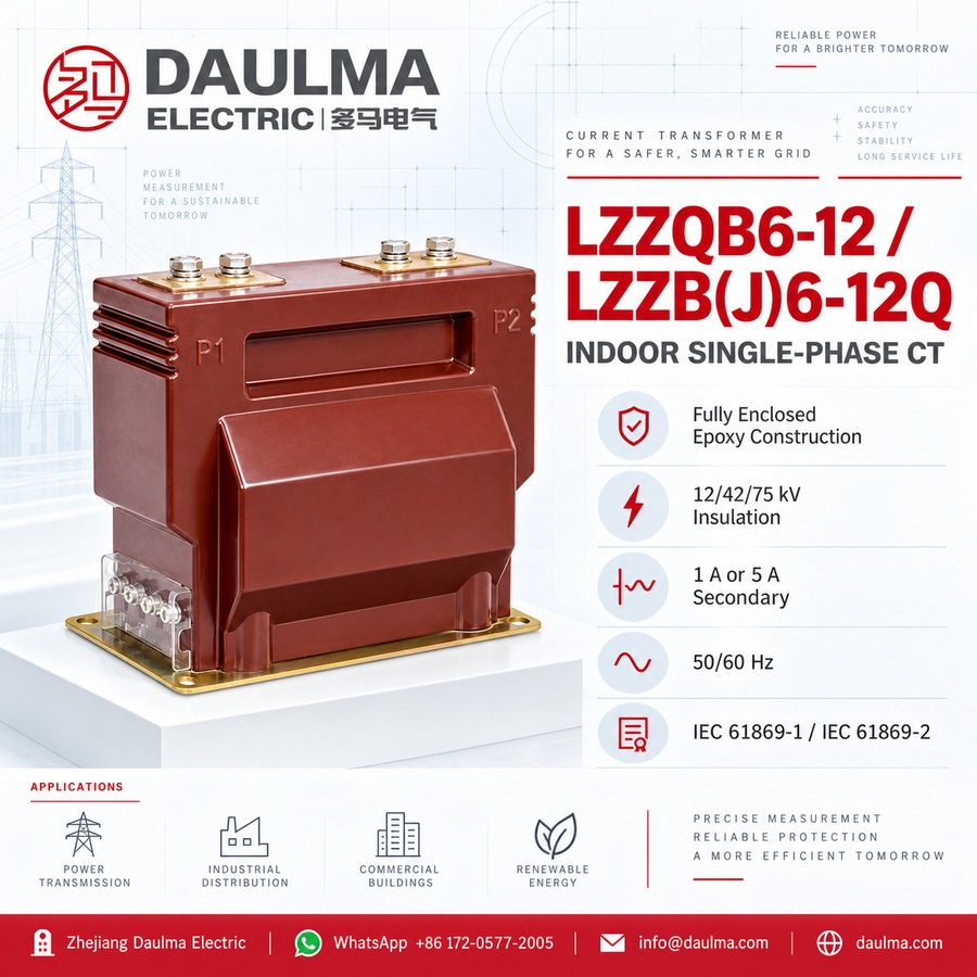
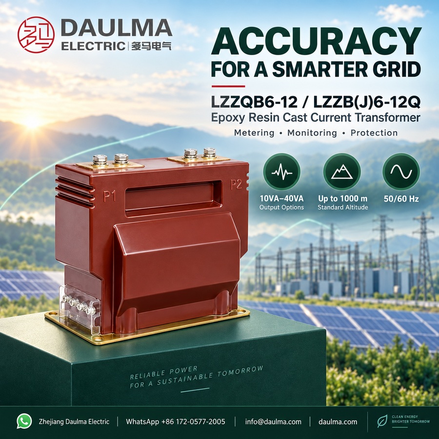
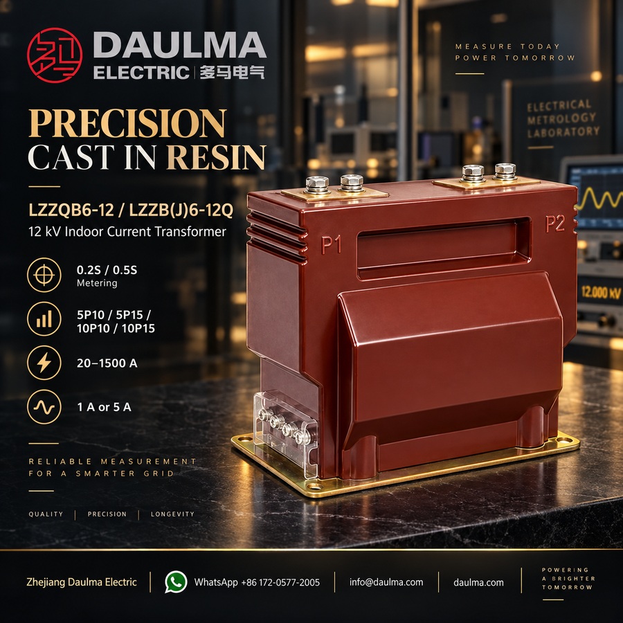
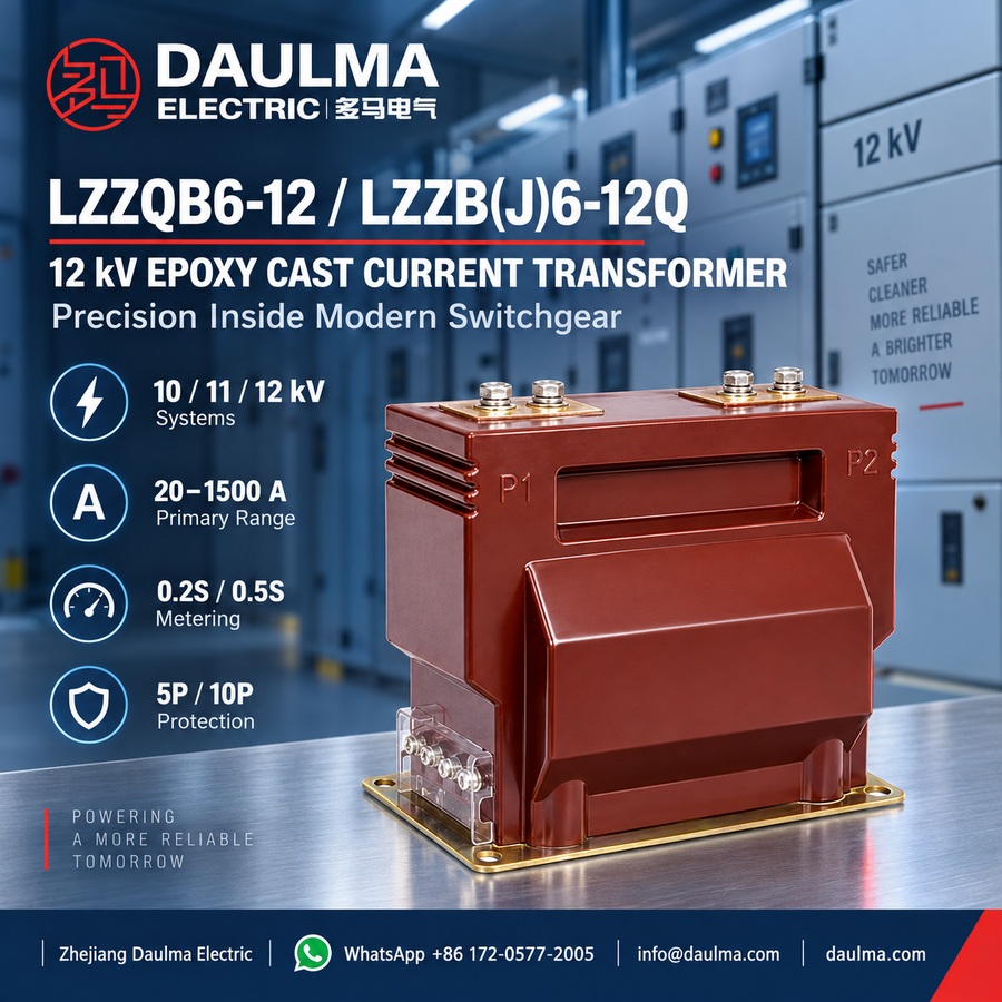
The LZZQB6-12 and LZZB(J)6-12Q are indoor, single-phase, epoxy resin cast current transformers designed for 10kV, 11kV, and 12kV medium-voltage systems. They feature a fully enclosed cast-resin structure that encapsulates the primary winding, secondary winding, and magnetic core, ensuring high insulation strength, moisture resistance, and mechanical durability for indoor switchgear environments.
These transformers support both measurement (0.2S/0.5S) and protection (5P/10P) accuracy classes, making them suitable for energy metering, relay protection, feeder monitoring, and SCADA integration. They comply with IEC 61869-1 and IEC 61869-2 standards and operate reliably in 50Hz or 60Hz AC systems with 12kV-class insulation coordination.
Key Ratings Snapshot
| Parameter | Rating |
|---|---|
| Voltage class | 10kV / 11kV / 12kV |
| Highest voltage for equipment | 12kV |
| Rated insulation level | 12/42/75kV |
| Rated frequency | 50Hz / 60Hz |
| Rated secondary current | 1A or 5A |
| Measurement accuracy class | 0.2S, 0.5S |
| Protection accuracy class | 5P10, 5P15, 10P10, 10P15 |
| System type | Single-phase, indoor |
| Insulation material | Epoxy resin cast |
| Application standard | IEC 61869-1, IEC 61869-2 |
| Installation environment | Indoor switchgear |
| Primary function | Current measurement, energy metering, relay protection |
Model Designation
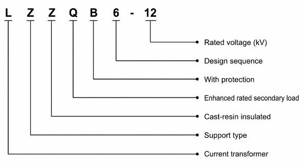
- L: Current transformer
- Z: Support type / post-type structure
- Z: Cast-resin insulated / fully enclosed structure
- Q: Enhanced structure or Q-series design platform
- B: With protection function / protection-class configuration available
- J: Reinforced or extended-rated secondary load design according to model configuration
- 6: Design sequence
- 10 / 12: Voltage class identification; LZZQB6-10 for 10kV-class projects, while LZZQB6-12 / LZZB(J)6-12Q / LZZBJ6-12 are for 12kV-class insulation coordination covering 10kV, 11kV, and 12kV applications
Construction
The LZZQB6-12 and LZZB(J)6-12Q current transformers feature an indoor, single-phase, fully enclosed support-type construction. The primary winding, secondary winding, and magnetic core are completely embedded within a solid epoxy resin cast body. This cast-resin insulation provides excellent dielectric strength, resistance to humidity and contamination, and robust mechanical support for indoor medium-voltage switchgear installations. The compact, seamless housing eliminates air gaps and surface tracking paths, enhancing long-term reliability under continuous operation in 50Hz or 60Hz AC systems rated up to 12kV.
Technical Parameters
Service Conditions
- Installation location: indoor medium-voltage switchgear
- System voltage: 10kV, 11kV, or 12kV class
- Rated frequency: 50Hz / 60Hz
- Rated insulation level: 12/42/75kV
- Ambient temperature: -5°C to +40°C
- Altitude: not exceeding 1000m under standard service conditions unless otherwise specified
- Installation environment: should be free from severe vibration, corrosive gas, explosive medium, heavy pollution, and abnormal condensation.
- Special applications: for high altitude, high humidity, coastal, heavy-pollution, or special switchgear applications, technical confirmation is recommended before ordering.
Technical Parameters
The LZZQB6-12 and LZZB(J)6-12Q are epoxy resin cast current transformers designed for indoor medium-voltage switchgear applications. They operate within a rated voltage class of 10–12kV, with an ambient temperature range of -5°C to +40°C and standard service up to 1000m altitude. Compliant with IEC 61869-1/-2 (and IEC 60044-1 for legacy reference), they support primary currents from 20A to 1500A and offer flexible secondary configurations for metering and protection.
Technical Data
| Rated Primary Current (A) |
Accuracy Class Combination |
MeteringOutput 0.2S / 0.5S (VA) |
Metering Output 0.5 (VA) |
Protection Output 5P15 / 10P15 (VA) |
Short-Time Thermal Current |
Rated Dynamic Current |
Weight Reference |
|---|---|---|---|---|---|---|---|
| 20–100 | 0.2S / 0.5S 0.2S / 10P 0.5S / 10P |
10 | 15 | 15 | 150 × I1n | 375 × I1n | Approx. 28kg |
| 150–300 | 15 | 20 | 31.5kA | 80kA | |||
| 400 | 20 | 30 | 31.5kA | 80kA | |||
| 500–600 | 20 | 30 | 44.5kA | 80kA | |||
| 800 | 30 | 40 | 63kA | 100kA | |||
| 1000–1500 | 30 | 40 | 63kA | 100kA |
Note: The table is for preliminary engineering selection. If the secondary current is 1A or if the required parameters are beyond the listed range, the final current ratio, accuracy class, rated output, thermal current, dynamic current, and terminal arrangement shall be confirmed by technical agreement.
10P Accuracy Limit Factor and Burden Reference
| Rated Primary Current (A) |
Typical Protection Class |
Rated Output (VA) |
Application Note |
|---|---|---|---|
| 30–75 | 0.2 / 10P, 0.5 / 10P | 10 / 15 or 15 / 20 | Low-current feeder protection and metering circuits |
| 100–300 | 0.5 / 10P15 | 15 / 20 | Standard feeder metering and protection configuration |
| 400–600 | 0.2 / 0.5 / 10P15 | 20 / 20 / 30 or 30 / 30 | Medium-current switchgear protection applications |
| 800–3150 | 0.5 / 10P15 | 30 / 30 or 40 / 40 | High-current feeder and main incoming panel applications |
Installation & Wiring
Installation Diagram
Terminal Marking and Function
| Terminal Marking | Function | Application Note |
|---|---|---|
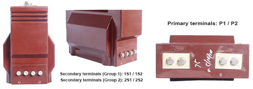
| P1 / P2 | Primary terminals | The reference primary current direction is normally defined from P1 to P2. |
| 1S1 / 1S2 | First secondary winding | Usually used for metering, measurement, or the first specified secondary core. |
| 2S1 / 2S2 | Second secondary winding | Usually used for relay protection or an additional secondary circuit when required. |
| Secondary terminal cover |
Secondary wiring protection | The protective terminal cover helps reduce accidental contact and supports safer wiring maintenance. |
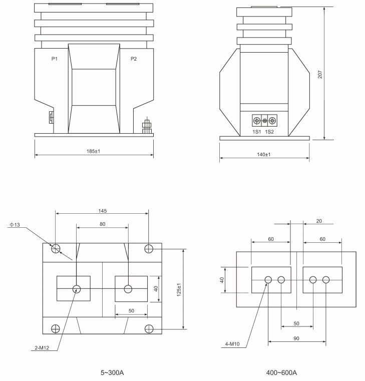
The LZZQB6-12 and LZZB(J)6-12Q current transformers are designed for indoor installation in medium-voltage switchgear. They feature a cast-resin fully enclosed support-type structure mounted via a base plate with pre-drilled mounting holes. Primary terminals (P1/P2) and secondary terminal blocks with protective covers are positioned as per the approved outline drawing to ensure compatibility with switchgear layout, phase clearance, and wiring access.
Selection & FAQs
Selection Guide
- Confirm the 12kV highest equipment voltage and 12/42/75kV insulation level for the 10kV, 11kV or 12kV indoor switchgear system.
- Select the primary ratio from maximum continuous load, normal operating range, fault study and required metering resolution; confirm ratios outside the 20A–1500A reference range.
- Specify 1A or 5A secondaries and assign each core to metering, measurement or protection with the required 0.2S/0.5S or 5P/10P class.
- Add instrument/relay and secondary-cable burdens, then select 10VA–40VA output with the required FS or protection accuracy-limit factor.
- Verify short-time/dynamic current, number of cores, P1/P2 orientation, terminal layout, base dimensions, phase clearances, altitude and indoor environment.
Frequently Asked Questions
Q1: Can this epoxy resin CT be installed outdoors?
No, this epoxy resin cast current transformer is strictly designed for indoor medium-voltage switchgear. The environment must be free from corrosive gases and abnormal condensation. Please contact us for outdoor alternatives.
Q2: What is the rated insulation level for 12kV systems?
The rated insulation level is 12/42/75kV. This ensures reliable performance within 10kV, 11kV, and 12kV class systems. It maintains dielectric strength under standard indoor service conditions.
Q3: Which primary current range is available for protection circuits?
Primary currents range from 20A to 1500A to support both metering and protection. Secondary configurations are flexible based on your relay requirements. Specify your exact ratio during inquiry.
Q4: Are these current transformers compliant with international IEC standards?
Yes, they fully comply with IEC 61869-1 and IEC 61869-2 standards. They also reference legacy IEC 60044-1 specifications. Request the specific type test reports for your project documentation.
Q5: Can this 12kV CT operate at altitudes above 1000m?
Standard service is limited to altitudes not exceeding 1000m. For high-altitude or heavy-pollution applications, technical confirmation and design adjustments are required. Submit your site conditions for factory evaluation.
Q6: What applications suit the LZZQB6-12 epoxy cast transformer?
It is ideal for indoor medium-voltage switchgear requiring accurate current measurement and protection. We manufacture these 10-12kV class epoxy resin units to fit specific panel designs. The epoxy casting provides excellent mechanical and dielectric strength.
Q7: How does the rated frequency affect the CT selection?
These transformers support both 50Hz and 60Hz rated frequencies. This flexibility allows integration into diverse global power grids without modifying the core design. The magnetic core is optimized for minimal loss at both frequencies.